
Build a Measured-to-Fit Tote Rack Without Guessing the Spacing
Specifies ten 61-1/4-inch uprights, thirty-two 32-inch runners, four 91-1/2-inch connectors and a 108-inch brace, plus runner heights.
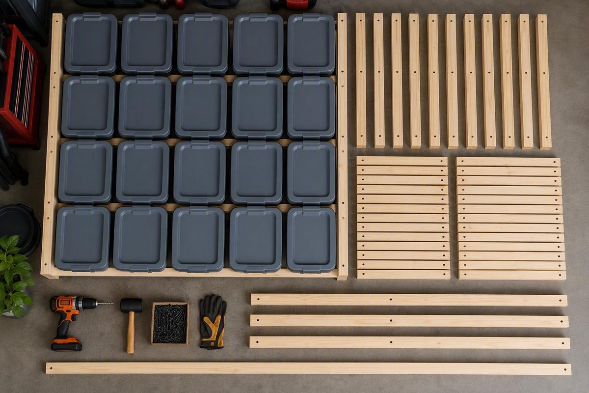
A tote rack lets you remove one container without unstacking the others, but the fit depends on more than the gallon label. “27 gallons” describes capacity—not a standardized exterior width, depth, height, lid profile, or supporting rim.
This guide uses the documented Project Source Commander layout as its primary plan: a 2x4 rack for 16 totes arranged four columns across and four rows high. Before cutting the full project, measure one of your exact totes with its normal lid and build a temporary test bay.
The primary source does not provide an independently tested per-position or total load rating. It also states that the rack is not intended to support totes loaded to full capacity. This article is therefore a source-based construction synthesis, not an engineering review or independent load test.
What This 16-Tote Rack Plan Builds
The primary design is a wooden, ladder-style rack for 16 Project Source Commander 27-gallon totes. Instead of placing each tote on a solid shelf, pairs of horizontal 2x4 runners support the projecting upper rim on the tote’s left and right sides.
That arrangement creates 16 independent positions. You can slide out one bin without removing the containers above it.
The rack uses five ladder assemblies:
- Two exterior ladders: Each carries runners on its inward-facing side only.
- Three interior ladders: Each carries runners on both sides.
- Four tote columns: Each opening lies between two adjacent ladders.
- Four runner levels: Each column holds four totes vertically.
Each ladder consists of a front upright and a rear upright. A 32-inch runner spans front to back between those uprights and attaches along one face of the ladder. On an exterior ladder, the runners are installed only on the face directed toward the tote openings. On an interior ladder, matching runners are installed on both faces so the ladder supports totes on its left and right.
The documented layout uses ten 61-1/4-inch uprights, thirty-two 32-inch runners, four 91-1/2-inch connecting boards, and one 108-inch rear diagonal brace. Runner tops are marked at 13-1/2, 28-1/2, 43-1/2, and 58-1/2 inches. Lowe’s published the plan on May 16, 2025, specifically for Project Source Commander totes and warns that it is not intended to hold totes loaded to full capacity (Lowe’s Commander tote-rack plan).
It is not the center-to-center pitch:
- Clear opening: 21 inches
- Upright thickness: 1-1/2 inches
- Repeated ladder pitch: 22-1/2 inches
- Four openings plus five upright thicknesses: 91-1/2 inches overall
That relationship matches the specified 91-1/2-inch top and bottom connecting boards. Do not substitute 21 inches as the pitch or measure 21 inches from the same edge of one upright to the same edge of the next; doing so would make the rack too narrow.
Based on the specified component geometry, the stationary frame is approximately:
| Dimension | Primary frame measurement | Limitation |
|---|---|---|
| Width | 91-1/2 inches | Matches four 21-inch openings plus five 1-1/2-inch uprights |
| Depth | 32 inches | Based on the runner length and ladder depth |
| Frame height | 61-1/4 inches | Based on the upright length |
| Mobile height | Not established exactly | A nominal 4-inch caster does not necessarily add exactly 4 inches to installed height |
Confirm the actual assembled dimensions before choosing the location. Fastener heads, brace position, caster plates, lumber distortion, and installation details can affect the practical clearance needed around the frame.
The plan can be configured as either:
- A stationary rack: Set on a level surface, rear-braced, and attached to suitable structural framing.
- An optional mobile rack: Fitted with four plate-mounted swivel casters with brakes.
The stationary version is the conservative choice when the rack will remain against a wall. Casters introduce additional questions involving wheel capacity, mounting strength, floor condition, movement, and tipping resistance. Locking wheels do not eliminate those considerations.
Measure the Tote and Garage Before Cutting
Measure the actual tote you plan to store rather than relying on its advertised capacity. If you own several apparently identical bins, measure more than one. Different lids, manufacturing variation, previous loading, and deformation can change the dimensions that determine whether a tote slides freely.
Install the lid that will normally remain on the tote, place the container on a flat surface, and record these measurements:
| Measurement | How to take it | Why it matters |
|---|---|---|
| Maximum front width | Measure the widest point across the lid, rim, handles, or latches | Determines the minimum usable opening |
| Overall depth | Measure the longest front-to-back dimension, including projections | Helps determine runner length and removal space |
| Overall height | Measure from the tote bottom to the highest point of the installed lid | Determines vertical spacing |
| Lip overhang | Measure how far the supporting rim projects beyond the tote body on each side | Determines how much rim can overlap each runner |
| Lip height or thickness | Measure the vertical size of the area that will engage the runner | Affects support and removal clearance |
| Handle projection | Measure any handle or latch extending beyond the lid or rim | Prevents collisions with the uprights |
| Loaded deformation | Observe whether expected contents cause the sides or rim to bow | Reveals dimensional changes not visible in an empty tote |
A measurement-driven configurator uses these same categories, including maximum front width, side length, overall height, lip overhang, lip height, and user-selected clearances. Its example defaults include 1 inch of vertical clearance and an additional 1/4 inch of horizontal spacing, but those are planning defaults rather than universal requirements (Ana White’s tote-rack configurator).
Inspect the part of the rim that will rest on the runners. A cracked, split, severely abraded, permanently bent, heat-deformed, or unusually flexible rim is a poor candidate for suspended storage. Measuring a tote with representative contents can reveal deformation, but a short fit test does not establish a safe load capacity.
Keep these three horizontal dimensions distinct:
- Maximum tote width: The widest point of the tote, lid, handles, or latches.
- Clear opening: The unobstructed space between the facing sides of two adjacent ladder uprights.
- Column pitch: The repeated distance from the same reference edge on one ladder to the corresponding edge on the next.
For the Commander layout, a 21-inch clear opening and a 1-1/2-inch upright produce a 22-1/2-inch pitch.
Measure the proposed installation area as carefully as the tote. Confirm that:
- The floor area accommodates the frame and any caster plates.
- The ceiling allows the rack to be assembled or raised into position.
- Doors, tracks, opener rails, pipes, electrical panels, windows, and vehicles will not interfere.
- Suitable structural framing is accessible for anchoring a stationary rack.
- The floor is reasonably level.
- There is room to pull the deepest tote completely off its runners.
- The top row remains practical to reach.
- The assembled rack can pass through the required doorway or rotate into place.
A large frame can fit along a wall yet remain impossible to maneuver through a doorway or under a low ceiling. If access is restricted, smaller independently braced and anchored modules may be more manageable.
Build a temporary fit bay
Before permanently fastening five ladders and all 32 runners, temporarily assemble one tote opening. Use two properly oriented ladder sections or two clamped uprights with parallel runners at the intended height.
Insert the actual tote and verify:
- The left and right rims overlap their runners.
- The tote sits evenly rather than leaning to one side.
- The lid, handles, and latches clear the uprights.
- The tote slides without wedging or scraping heavily.
- The runners support the rim through the intended depth.
- The rear of the tote does not collide with the brace or wall.
- There is enough vertical room for the motion required to remove the tote.
- The tote can be pulled fully forward in the final location.
This is a dimensional fit check only. It does not validate the structural capacity of the tote rim, fasteners, lumber, or completed rack.
Materials, Tools, and Complete Cut List for the 4-by-4 Rack
The following quantities and cuts apply to the 16-position Commander configuration. They are not a universal shopping list for every tote labeled 27 gallons.
Lumber and fasteners
Purchase:
- Twenty-two 2x4x8 boards
- One 2x4x10 board
-
10 x 2-1/2-inch exterior wood screws
The documented cut list contains one 108-inch brace, ten 61-1/4-inch uprights, thirty-two 32-inch runners, and four 91-1/2-inch connecting supports. The optional mobile version adds four 4-inch plate-mount swivel casters with brakes and sixteen 5/16-inch x 1-1/2-inch lag screws (Lowe’s tools, materials, and assembly instructions).
The supplied evidence does not establish a universal total screw count or a complete screw-placement pattern for every runner-to-upright and connecting-board joint. It specifies the screw size and states that the rear brace receives two screws at each ladder crossing, but it does not support inventing a fastening schedule for the remaining joints. Consult the source diagrams and applicable fastener instructions before assembly; do not infer a load rating from screw quantity.
Select the straightest lumber available. Reject boards that are substantially bowed, twisted, split, cupped, or damaged around likely fastener locations. Warped uprights can produce leaning ladders, while twisted runners can create unequal rim contact and binding.
Complete 16-tote cut list
| Part | Quantity | Cut length | Purpose |
|---|---|---|---|
| Rear diagonal brace | 1 | 108 inches | Limits side-to-side frame distortion |
| Uprights | 10 | 61-1/4 inches | Form the front and rear of five ladders |
| Tote runners | 32 | 32 inches | Span front to back and support tote rims |
| Top and bottom connecting boards | 4 | 91-1/2 inches | Connect the five ladders across the front and rear |
The 108-inch brace requires the 10-foot board. The remaining parts are cut from the 8-foot boards within the source’s material allowance.
Plan the cuts before operating the saw. Account for blade kerf rather than assuming nominal board lengths can be divided with no material loss. Label each finished piece—“upright,” “runner,” “connector,” or “brace”—and group identical parts together to check for obvious length differences.
Tools and protective equipment
The plan’s tool list includes:
- Drill/driver
- Appropriate drill and driver bits
- Tape measure
- Miter saw
- Rafter square or speed square
- Screwdrivers
- Clamps
- Safety glasses
- Work gloves
- Hearing protection
A ratchet and socket set is useful for the optional caster hardware. Follow the manufacturers’ operating instructions for the saw, drill, fasteners, and casters.
Optional mobile-rack hardware
For the documented caster-equipped version, add:
- Four 4-inch plate-mount swivel casters with brakes
- Sixteen 5/16-inch x 1-1/2-inch lag screws
These specifications identify the plan components; they do not establish the capacity of the completed mobile rack. The selected wheels, plates, fasteners, and wood mounting locations must be appropriate for the entire loaded assembly.
Build the Five Ladder Assemblies and Position the Runners
Each ladder uses two 61-1/4-inch uprights—one at the front and one at the rear—with four 32-inch runners spanning between them at the specified elevations.
Work on a flat assembly surface so the front and rear uprights can lie in the same plane.
Mark the runner elevations
On every upright, measure from the same bottom end and mark the top edge of each runner at:
- 13-1/2 inches
- 28-1/2 inches
- 43-1/2 inches
- 58-1/2 inches
Use a square to carry each mark across the face that will receive the runner. Measure every elevation from the bottom baseline rather than measuring upward from the preceding runner. Chaining four measurements can accumulate small errors.
After verifying the first layout, transfer the four elevations to a straight story stick or spacer. Label its bottom so it cannot be reversed accidentally.
Understand the runner orientation
A runner is not a short cantilever projecting from a single upright. Each 32-inch runner runs front to back, joining the front and rear uprights of one ladder.
At one tote level:
- The left ladder supplies the tote’s left runner.
- The right ladder supplies the tote’s right runner.
- The tote slides front to back between those two ladders.
- An interior ladder carries one runner on each face at the same elevation because it serves a column on either side.
Viewed from above, the five ladders run front to back and divide the rack into four side-by-side openings. The four 91-1/2-inch connecting boards run left to right across the front and rear at the top and bottom.
Build the two exterior ladders
Lay two uprights parallel, spaced to accept the 32-inch runners front to back. Orient the runner-bearing face so it will point toward the tote openings after final assembly.
Position one runner at each marked elevation. Align the runner’s top edge with the layout line and use a square to keep it perpendicular to the upright. Attach both ends according to the source diagram and suitable fastener instructions.
Build the second exterior ladder as a mirror image. When the two exterior ladders stand at opposite ends of the finished rack, all runners must face inward.
Build the three interior ladders
Each interior ladder receives runners on both faces at all four levels. The two runners at a given elevation should be aligned so the adjacent totes sit at the same height.
The full runner distribution is:
- First exterior ladder: 4 runners
- First interior ladder: 8 runners
- Second interior ladder: 8 runners
- Third interior ladder: 8 runners
- Second exterior ladder: 4 runners
That totals 32 runners, or eight runner pieces at each of the four elevations.
Verify before duplicating
A reliable workflow is to complete one ladder or temporary bay before assembling every repeated part. Check that:
- The front and rear uprights are parallel.
- Each runner is square to its uprights.
- Matching left and right runners share the same elevation.
- The tote rim engages both runners.
- The lid and handles clear the frame.
- The tote can be inserted and removed without excessive lifting.
Matching cut lengths do not guarantee square construction. A frame assembled out of square can become a parallelogram even when every board is the correct length.
Join, Square, Test-Fit, and Brace the Rack
Arrange the completed ladders in this order:
- Exterior ladder with runners facing inward
- Interior ladder with runners on both faces
- Interior ladder with runners on both faces
- Interior ladder with runners on both faces
- Exterior ladder with runners facing inward
Connect them with the four 91-1/2-inch boards:
- One across the front at the top
- One across the rear at the top
- One across the front at the bottom
- One across the rear at the bottom
The supplied evidence specifies the screw type but does not provide a complete, independently validated screw count and placement pattern for these ladder-to-connector joints. Follow the source diagram rather than improvising a claimed universal fastening schedule.
Establish the 21-inch clear openings
The width relationship is:
4 openings × 21 inches + 5 uprights × 1-1/2 inches = 91-1/2 inches
Use a verified 21-inch spacer between facing upright surfaces if practical. Check the opening at both the top and bottom. Different measurements indicate that the ladders are not parallel.
Temporarily fasten or clamp the first two ladders before committing to the remaining three.
Test the first connected bay
Slide the actual tote onto the first runner pair and check:
- Rim engagement: Both sides rest on their respective runners.
- Side clearance: The lid, rim, handles, and latches do not bind against the uprights.
- Depth: The tote reaches its intended position without striking the rear brace or wall.
- Removal clearance: The tote can move forward and disengage without colliding with the level above or nearby garage features.
View the tote from the front. It should sit evenly. Unequal resistance can indicate mismatched runner elevations, a twisted runner, nonparallel ladders, or insufficient opening width.
Once the first bay fits, use its verified geometry to place the remaining ladders. Check each 21-inch opening instead of assuming that repeated measurements cannot drift.
Square the complete frame
Check square during assembly, before fully tightening permanent connections. Compare diagonals where the geometry allows and check the uprights for consistent alignment.
If a tote fits at the front but wedges farther back, the likely issue is not simply “a narrow rack.” The front and rear uprights may be out of parallel, a runner may be twisted, or the connecting boards may be pulling the frame out of square.
Install the rear diagonal brace
After confirming the frame and tote openings, install the 108-inch brace diagonally across the rear—from the top of one exterior ladder to the bottom of the opposite exterior ladder.
The documented plan calls for two screws at every ladder crossing. Install the brace while the frame is held square; otherwise, the brace can preserve an out-of-square condition.
Rear bracing and wall attachment perform different jobs:
- The diagonal brace limits side-to-side racking within the wooden frame.
- Wall attachment limits movement or forward tipping of the whole rack.
- A level base reduces rocking and unwanted frame distortion.
- Conservative loading reduces stress and keeps heavier mass lower.
One measure does not replace the others.
Anchor and Load the Rack Conservatively
Place a stationary rack on a reasonably level, stable surface. If the frame rocks or twists after being moved into place, correct the installation before loading totes.
The stationary Commander instructions call for attaching the rack to a wall with furniture straps to reduce tipping risk. The correct fastener depends on the wall construction. Wood framing, concrete, brick, and concrete block require different attachment systems.
Connect the anti-tip hardware to suitable structural framing rather than relying on drywall, trim, pegboard, or thin paneling. If the wall structure or appropriate attachment method cannot be identified, obtain installation guidance for that substrate rather than guessing.
Do not assign this rack a per-tote or total weight limit. None of the cited plans provides independently tested structural capacity, and the Commander source explicitly warns that the rack is not intended to support totes loaded to full capacity.
Performance can vary with:
- Lumber species, grade, knots, cracks, moisture, and distortion
- Fastener type, condition, placement, and installation
- Joint geometry
- Frame squareness
- Runner alignment
- Tote-rim profile, stiffness, age, and damage
- Load distribution
- Bracing and anchoring
- Floor condition
- Caster and mounting details
Follow the source’s loading order: place heavier totes in the lowest positions and lighter totes above. This keeps more mass near the floor and reduces the need to handle dense containers at shoulder height.
Upper positions are better reserved for lighter, less frequently used contents.
Unload an affected position if you observe strain or movement, including:
- A runner rotating, splitting, sagging, or separating
- A joint opening
- An upright moving out of alignment
- The rack rocking or leaning
- The diagonal brace shifting
- A tote rim cracking, whitening, bending, or slipping
- New binding that was not present during the initial fit check
Repair or replace the affected component before using that position again. Do not add weight to investigate visible movement.
Resize the Design for Eight, Nine, or a Custom Number of Totes
Do not resize the 16-position rack by deleting parts while retaining every other dimension. Runner length, clear opening, vertical spacing, connecting-board length, and overall dimensions must match the tote and chosen layout.
The following documented examples show why “27 gallon” is not enough information by itself.
Documented eight-tote plan for approximately 30.6-by-20.6-by-14.3-inch bins
One freestanding design holds eight totes in two columns and four rows. It uses three ladder assemblies: two exterior assemblies and one center assembly.
Its cut list is:
| Part | Quantity | Length |
|---|---|---|
| Runners | 16 | 30.75 inches |
| Uprights | 6 | 62 inches |
| Top and bottom connecting boards | 4 | 47 inches |
The rack uses standard 2x4 lumber and 2.5-inch construction screws. Runner tops are marked at:
- 13.25 inches
- 28.75 inches
- 44.25 inches
- 59.75 inches
The center assembly carries runners on both faces, while the outer assemblies carry runners only on their inward faces. The source recommends measuring the actual totes because small dimensional differences can affect sliding clearance (HandBuilt’s eight-tote plan).
This design is conceptually similar to the Commander rack, but its runner length, upright length, connecting boards, and runner elevations are different. Those dimensions should not be mixed between plans.
Separate 2-by-4 example using a formula-based layout
Another demonstrated eight-tote rack measures 45.5 inches wide, 30 inches deep, and 72 inches high. It holds two columns by four rows.
Its plan-specific formulas are:
- Overall width: 22 inches × number of columns + 1.5 inches
- Overall height: 17 inches × number of rows + 4 inches
For two columns, the width formula produces 45.5 inches. For four rows, the height formula produces 72 inches. The corresponding cut list contains four 45.5-inch pieces, sixteen 30-inch supports, and six 69-inch vertical pieces (DIY for Home and Life’s tote-rack tutorial).
These formulas belong to that tutorial. They are not universal sizing rules and should not replace the Commander rack’s 21-inch clear opening.
The tutorial distinguishes among:
- A 22-inch repeated layout interval
- A 20.5-inch clear opening
- A 45.5-inch overall width for two columns
Confusing clear opening, pitch, and total width can make a rack too narrow or unnecessarily wide.
Configurable nine-position example
A separate measurement-driven configurator displays a three-column-by-three-row example with:
- 59.25-inch overall width
- 24-inch depth
- 39.5-inch height
- Eighteen 24-inch runners
- Eight 36.5-inch legs
- Four 59.25-inch rails
- Two 8.5-inch spacer blocks
- 17.75-inch calculated clear openings
- An estimated 88 screws
Those numbers illustrate configurable output, not universal dimensions for a nine-bin rack. The configurator also notes that not every generated tote or rack size has been tested.
A practical custom-sizing process
For an unlisted tote model:
- Measure the tote. Record maximum width, depth, height, lip geometry, handles, and visible loaded deformation.
- Choose its orientation. Decide which end will face outward and verify that the side rims can engage runners.
- Set a trial opening. Base it on the tote’s maximum width plus a small fit allowance appropriate to that tote.
- Choose runner length. Support the usable rim while retaining front access and rear clearance.
- Set the first elevation. Account for the lower frame and practical handling clearance.
- Set the vertical pitch. Include tote height, lid profile, rim position, and removal motion.
- Build one bay. Temporarily connect two ladders and insert the real tote.
- Correct the prototype. Adjust opening width, runner height, or depth before duplicating it.
- Repeat from shared references. Use a verified spacer or story stick rather than chained measurements.
- Brace and anchor the finished module. Confirm square before installing the brace.
Consider separate modules when one wide rack would be difficult to square, move, rotate, or attach. Each module still needs appropriate bracing and anti-tip consideration.
No single interval—21 inches, 22 inches, or another figure—is correct merely because a container is labeled 27 gallons. The final opening should come from the exact tote and a physical fit check.
Mobile Racks, Full Shelves, and Common Fit Problems
The documented mobile option uses four 4-inch plate-mount swivel casters with brakes, attached with sixteen 5/16-inch x 1-1/2-inch lag screws.
That hardware list does not establish the capacity or stability of the completed mobile rack. Caster selection must account for the combined rack, fasteners, totes, and contents, as well as potentially uneven load distribution among the wheels.
Check the selected caster manufacturer’s capacity and installation requirements. The frame must provide suitable mounting locations for the plates and lag screws. Do not create a rack rating by multiplying a wheel’s advertised capacity by four; the cited plans do not establish that calculation as a safe completed-rack limit.
Use a mobile configuration only where the floor allows controlled movement. Wheel brakes resist wheel rotation, but they do not prove that the frame cannot tip, rack sideways, or move under every condition.
As a conservative operating practice, avoid concentrating heavy contents in upper rows and unload the rack before relocation when practical. If caster capacity, mounting strength, floor suitability, or stability cannot be established, use the stationary anchored configuration.
When lip-supported runners are appropriate
A runner rack depends on a sufficiently projecting and intact rim. Both sides must engage reliably.
Identify which molded part actually rests on the runner; do not assume that the lid itself is structural. Inspect the supporting area for:
- Cracks
- Stress whitening
- Permanent bending
- Heat deformation
- Severe abrasion
- Shallow overlap
- Unequal projection
- Noticeable flexibility
A tapered tote body can appear to fit even when the upper rim barely overlaps the runners. Check engagement at both the front and rear.
When to use full shelves instead
A full-shelf design is a more conservative alternative when:
- The rim is cracked or damaged.
- The lip is too shallow to engage both runners reliably.
- The supporting plastic flexes noticeably.
- The tote is expected to hold dense contents.
- Its shape changes substantially when loaded.
- Several tote models with different rim profiles must share the rack.
- Bottom support is preferred over rim suspension.
Adding shelves changes the design. The shelf panels, supports, fasteners, frame, bracing, and anchoring must be appropriate for the revised construction; shelves should not be treated as a cosmetic addition to the runner plan.
Troubleshooting a tote that binds
If a tote does not slide smoothly:
- Verify the frame is square. Compare the opening at the top and bottom.
- Compare runner elevations. Measure both sides from the same bottom baseline.
- Check the runners with a square. A tilted runner can lift or pinch the rim.
- Inspect the lumber. Look for twisted runners and bowed uprights.
- Confirm the clear opening. Measure between facing upright surfaces at the front and rear.
- Inspect the tote. Check its lid, handles, latches, and sidewall deformation.
- Compare rim engagement. Make sure one side is not riding above or outside its runner.
- Review cumulative layout error. Confirm that each ladder was positioned from a shared reference.
- Loosen temporary connections. Correct the first inaccurate bay before tightening the rest.
- Retest in the installation location. Floor irregularity or wall attachment can alter frame alignment.
Do not plane away so much runner material that the tote loses meaningful overlap. Do not widen one bay without accounting for the connecting-board length, adjacent openings, brace geometry, and total rack width.
Visually check the installed rack after movement, loading changes, new binding, or observed damage. Look for loose fasteners, frame lean, brace movement, caster wear, moisture damage, split lumber, altered runner alignment, and cracked tote rims. The sources do not establish a universal inspection interval.
Frequently Asked Questions
Are all 27-gallon totes the same size?
No. Twenty-seven gallons describes capacity, not standardized exterior dimensions. Totes can differ in lid width, depth, height, handle projection, rim thickness, and lip overhang.
One commercial compatibility listing includes nominally 27-gallon totes ranging from approximately 28.5 to 30.75 inches long, with corresponding differences in width and height (Hudson’s Timber compatibility listings).
Measure the exact tote with its normal lid and verify it in a temporary bay before building the full rack.
How much weight can a wooden 27-gallon tote rack hold?
There is no supported universal answer for the plans discussed here. None provides an independently tested per-position or total structural capacity, and the primary Commander plan states that its rack is not intended to support totes loaded to full capacity.
Performance depends on the lumber, joints, fasteners, frame geometry, bracing, anchoring, tote rims, load distribution, and condition of the completed assembly. Do not derive a rack rating by dividing screw or caster ratings among the tote positions.
Load conservatively, keep heavier totes low, and unload any position showing movement, cracking, sagging, or other strain.
Does a tall tote rack need to be anchored to the wall?
The stationary Commander instructions call for wall attachment with furniture straps to reduce tipping risk. A configurable plan likewise warns that tall racks can tip forward and recommends attaching larger configurations through bracing into wall studs.
The correct hardware depends on the wall construction. Wood framing and masonry require different fasteners, and drywall or thin wall coverings should not be treated as structural attachment points.
Rear diagonal bracing does not replace anti-tip attachment. Bracing limits distortion within the rack; anchoring limits movement of the rack as a whole.
Can I put locking casters on a 27-gallon tote rack?
Yes. The primary plan includes an optional version with four 4-inch plate-mounted swivel casters with brakes and sixteen specified lag screws.
Locking wheels do not automatically establish adequate capacity or stability. The wheel ratings, mounting plates, fasteners, wood attachment points, floor condition, rack weight, and tote contents all matter.
If those factors cannot be established for the intended use, choose the stationary anchored version.
Are paid tote-rack plans better than free plans?
Not necessarily. A paid plan may offer diagrams, cut lists, calculators, multiple layouts, or seller support, but price does not establish structural testing or compatibility with a particular tote.
For example, one marketplace listing advertises a downloadable PDF with instructions, diagrams, a cut list, and multiple sizing options (Etsy tote-rack plan listing). Another listing advertises a calculator and numerous layouts, but its page is inconsistent about whether the purchase contains five PDFs or 16 plans (customizable Etsy plan listing).
Evaluate any free or paid plan by what it actually supplies:
- Exact tote dimensions or model compatibility
- Finished rack dimensions
- Complete cut list
- Runner elevations
- Clearly defined opening and pitch measurements
- Joint and hardware details
- Bracing instructions
- Anchoring guidance
- Caster requirements, if applicable
- A resizing method
- Physical test-fit instructions
- Clear disclosure of untested capacity
A free tote-specific plan that you verify physically may be more useful than a paid download with attractive drawings but incomplete compatibility or safety information.
Measurement-First Build Checklist
Before calling the rack complete:
- Verify the exact tote and lid.
- Measure the installation area and tote-removal path.
- Cut the documented parts for the tote-specific plan.
- Build one square temporary test bay.
- Confirm rim engagement, side clearance, depth, and removal clearance.
- Duplicate the verified layout from shared baselines.
- Maintain 21-inch clear openings—not 21-inch pitch—for the Commander layout.
- Square the full frame before installing the brace.
- Install the 108-inch rear diagonal brace.
- Attach a stationary rack to suitable structural framing.
- Place heavier totes in lower positions and lighter totes above.
- Stop using any position that shows frame movement, fastener strain, runner damage, or tote-rim deterioration.
The published dimensions remove much of the arithmetic, but they remain specific to the tote and layout for which they were developed. Measure the real container, test one bay before duplication, and do not treat any cited plan as having a tested weight capacity.