
What That Blinking Sensor Light Is Telling You—and How to Fix It Safely
Clear the beam and clean the lenses, then check the LEDs against the exact model's manual. If the light steadies only in shade, suspect light interference.
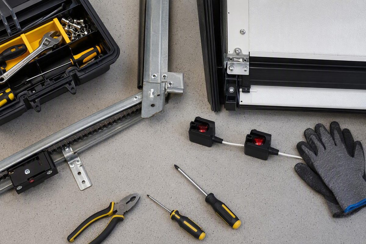
Quick answer: flashing red usually signals a fault, but color alone is not a diagnosis
A garage door sensor flashing red generally means the photo-eye safety system is not operating in its normal state. The light alone, however, does not identify the failed part or exact cause.
Possible causes include:
- An object blocking the infrared beam
- Dust, cobwebs, condensation, or moisture on a lens
- Sensors that no longer point directly at each other
- A bracket shifted by a bicycle, vehicle, tool, pet, or stored item
- Direct sunlight, glare, or a reflection reaching the receiver
- A loose electrical connection
- Cut, pinched, corroded, chewed, or otherwise damaged low-voltage wiring
- A failed sensor
- A problem within the opener head
Do not assume every red indicator is bad. On some systems, a solid red or amber sending light paired with a solid green receiving light can represent normal operation. Flashing, flickering, dimming, or an unexpectedly dark LED is more diagnostically useful than color alone, and the expected pattern varies by brand and model. This model variation is outlined in this sensor-color overview.
Before adjusting or disconnecting anything, record:
- The opener’s brand and exact model number
- Which sensor is flashing—the left or right unit, or the sender or receiver if labeled
- What the opposite sensor’s LED is doing
- Whether the flashes are continuous or form a repeatable count
- What the door does when you try to close it
For example, note whether the door refuses to move downward, starts closing and reverses, closes only while the wall control is held, or fails at a consistent time of day.
Those observations are more useful than “the light is red.” The sequence below helps narrow the problem safely, but it is not a universal light-code chart.
How the photo-eye safety system controls closing
Most automatic garage-door systems use two small photo-eye units mounted opposite each other near the bottom of the opening. One sends an invisible infrared beam across the doorway, and the other receives it.
When the receiver detects the beam, the opener can recognize that the monitored path is clear. If something interrupts the beam—or the receiver cannot detect it because of dirt, misalignment, glare, wiring trouble, or component failure—the opener may prevent the door from closing or reverse a door that has started downward.
Typical sensor-system symptoms include:
- Refusal to close
- Immediate reversal after the door starts down
- Blinking, flickering, or dark sensor LEDs
- Closing only while the wall control is continuously held
The low-mounted sender-and-receiver arrangement, infrared beam, and these common operating symptoms are described in this photo-eye troubleshooting guide.
The sensors must maintain:
- Electrical power and intact connections
- A clear path between the lenses
- Correct orientation and mounting position
- A signal the opener recognizes as valid
Problems in those areas can look alike from the wall control. A dirty receiver and a damaged conductor, for example, may both prevent normal closing even though the required repairs are different.
The photo eyes are part of the opener’s entrapment-protection system, not an optional parking aid. Never remove, disconnect, cover, reposition, or wire around them to defeat their function. Do not aim them away from the opening or mount them higher merely to avoid a recurring obstruction. Permanently bypassing the sensors removes the system’s ability to detect an object in the monitored path and is specifically discouraged in garage-door safety guidance.
A door that closes after its sensors have been defeated has not been repaired. It is operating without the intended protection.
Identify the opener before interpreting the light
Start at the opener’s motor head—the unit suspended from the ceiling. Find its product label and photograph the:
- Brand
- Model number
- Serial number, if present
- Manufacturing or date code, if shown
Then inspect the sensor housings without disconnecting them. Look for a manufacturer name, part number, model designation, or molded label. If replacement sensors were installed previously, their markings may help determine whether they are compatible with the opener.
Use the exact model number to find the owner’s manual or manufacturer support documentation. The correct instructions should explain:
- Which unit sends and which receives
- What each LED looks like during normal operation
- Whether flashing is continuous or forms a counted diagnostic code
- What each documented pattern means
- The required sensor position and mounting height
- Whether a reset is appropriate and how to perform it
- Which replacement sensors or kits are approved
Do not identify the sender and receiver from LED color alone. Some product families use red and green, others amber or yellow and green, and the arrangement can vary between generations. A chart for a visually similar opener may not apply to yours.
A bounded Genie example
For Genie Safe-T-Beam systems specifically, Genie says a flashing red LED indicates a malfunction. Its initial checks include cleaning the lenses, removing obstructions, checking for loose wires, and confirming that the sensors are aligned. Genie also says the opposing lenses should face one another and describes mounting them five to six inches above the floor for the cited setup. If flashing continues, Genie directs the owner to the opener’s manual for further model-specific troubleshooting in its Safe-T-Beam support guidance.
That guidance is useful for the named Genie system. It should not be treated as a universal rule for every red LED.
The same limitation applies to blink counts. Certain opener families may use counted flashes to distinguish an open wire, short, reversed conductors, or misalignment, but those meanings are not universal. Record any repeatable count and interpret it only through documentation for the exact opener.
The manufacturer or a garage-door technician may be able to identify the equipment from those details.
Use the symptom pattern to choose the first check
Treat both sensor lights and the door’s behavior as one diagnostic pattern. The table below suggests where to begin without assigning a universal meaning to a particular color.
| What you observe | First checks | What it may indicate |
|---|---|---|
| One LED flashes while the other remains steady | Clear the beam, clean and dry both lenses, check alignment, and consult the model’s blink code | An obstructed or undetected beam, misalignment, glare, or a model-specific wiring fault |
| One LED is completely dark | Check that sensor’s visible connection and accessible wiring; compare the condition with the manual | Loss of power, an open connection, wiring damage, or sensor failure |
| Both LEDs are dark | Confirm the opener is plugged in; check for an outage or tripped breaker or fuse; inspect visible sensor connections | Opener power loss, disconnected sensor wiring, or a fault affecting the sensor circuit |
| Flashing occurs at a consistent time of day | Observe where sunlight or reflections land and perform a temporary shade test | Direct sun, glare, or reflected light affecting the receiver |
| The door starts down and reverses immediately | Check the doorway, lenses, sensor aim, brackets, and visible wiring | Failure to receive a valid clear-path signal, although another door or opener problem is possible |
| The door closes only while the wall control is held | Restore normal sensor operation rather than relying on hold-to-close | A sensor-system problem that prevents normal automatic closing |
| Both LEDs appear normal, but the problem remains | Perform the manual’s functional test and seek deeper diagnosis if it fails | Intermittent wiring, sensor failure, opener-head trouble, or a separate door-system fault |
One flashing LED and one steady LED
Begin with the parts the sensors share: the beam path and alignment. Remove obstructions, clean and dry both lenses, and check whether the brackets still face each other.
If those checks do not help, consult the model’s diagnostic table before deciding that the flashing unit has failed. The flashing sensor may be reporting that it cannot detect the opposing unit or that the opener recognizes a circuit problem.
One dark LED
A dark LED calls for a power and connection check before alignment. Inspect the accessible wire and connection associated with that sensor. A unit receiving no power cannot be brought back into operation by rotating its bracket.
Compare “dark” with the manual’s normal indicator state. Some models may use different LED behavior in different operating conditions.
Both LEDs dark
Do not begin by loosening both brackets. First verify that the motor head is plugged into a working supply. Check for a power outage and inspect the relevant breaker or fuse.
If the opener itself has no power, the fault extends beyond photo-eye alignment. If the motor head operates but both sensor indicators are unexpectedly dark, visible sensor connections and model-specific wiring should be checked next.
The fault occurs at the same time each day
A morning-only or afternoon-only problem may be associated with sunlight, glare, or reflections. Watch for low-angle light shining into one lens or reflected light from a vehicle, glass, or another bright surface.
Temporarily cast a shadow over the receiver without blocking its view of the opposing sensor. If the indicator stabilizes only while shaded, light interference is a plausible cause. Direct sunlight and a temporary shade test are discussed in this sensor troubleshooting guide.
The door reverses as soon as it starts closing
Confirm that nothing crosses the beam at sensor height. Possible obstructions include a vehicle tire, trailer hitch, broom handle, hanging cord, leaf, bicycle pedal, or warped storage bin.
Then inspect the lenses, aim, and brackets. If the sensors show the expected normal indicators and pass the manufacturer’s functional test, the reversal may originate elsewhere in the door or opener system. Do not continue moving the photo eyes simply because they are easy to reach.
The door closes only while you hold the wall button
This behavior can indicate that normal sensor protection is unavailable. Treat it as diagnostic information, not as permission to make hold-to-close the routine operating method.
If the lenses are clean, the beam is clear, the sensors are aligned, and the LEDs show the expected state, possible next steps include diagnosis of an intermittent conductor, failed or incompatible sensor, or opener-head fault. LED color alone cannot safely distinguish among those possibilities.
Start with these no-tools checks: clear, clean, dry, and shade-test
Complete these noninvasive checks before loosening hardware or touching wiring. Recheck both sensor LEDs after each action. Changing several conditions at once can restore operation without revealing what caused the fault.
1. Clear the entire beam path
Look from one sensor to the other at sensor height, not merely through the middle of the doorway. Remove anything crossing or crowding that line, including:
- Leaves and grass clippings
- Cobwebs and accumulated dust
- Toys, balls, and pet items
- Tools, brooms, and extension cords
- Boxes, bins, and stored lumber
- Bicycle wheels or pedals
- Vehicle tires, bumpers, mirrors, or trailer components
- Snow, ice, or mud near the track
A small object can obstruct the beam while sitting outside the door panel’s apparent travel path. Check for loose materials that may move in a draft and cause an intermittent fault.
After clearing the path, inspect both indicators. Operate the door only if the LEDs now match the model-defined normal state. If either light continues to report a fault, keep the door stationary and proceed to the next check.
2. Clean both lenses gently
Use a soft, dry, lint-free cloth. Wipe each lens without twisting the sensor housing or pushing against its bracket.
If dry wiping does not remove the residue, use only a cleaning method permitted by the manufacturer. A slightly damp cloth or mild cleaner may be acceptable for some sensors, but avoid abrasive pads, rough paper, solvents, and harsh household chemicals. Dry both lenses completely.
Clean both units even if only one LED flashes. Dirt on the apparently normal unit can still interfere with the beam.
3. Check for moisture
Look for condensation, water droplets, dirt streaks, or fogging on each lens. Dry the exterior completely with a lint-free cloth.
Also look for evidence that water has reached the housing or nearby wiring:
- Rust or greenish corrosion
- Mineral marks
- Damp wire insulation
- Water visible inside a lens or housing
- Drips from a wall, roof, track, or weather seal
- A cracked or damaged sensor casing
Surface condensation may clear after drying. Water inside a sensor, substantial corrosion, or recurring leakage warrants professional diagnosis rather than repeated wiping.
4. Perform a temporary shade test
If the fault is intermittent or time-dependent, identify the receiving sensor from the manual or housing label. Use your hand or another opaque object to cast a shadow over it while keeping the direct line between the two lenses completely open.
Watch the LED. If it becomes stable only while shaded, sunlight or glare may be interfering with reception.
Treat this as a diagnostic test—not authorization for a permanent homemade cover. Do not tape cardboard to the sensor, enclose it, or alter the bracket unless the manufacturer approves the shield or installation method.
5. Compare the result after every step
Follow a controlled sequence:
- Record both LED states.
- Make one change.
- Observe both LEDs again.
- Operate the door only if the indicators match the manual’s normal state.
- Continue troubleshooting if the fault remains.
If removing a cobweb changes a flashing LED to its expected steady state, you have evidence that the beam was obstructed. If cleaning, drying, and shade-testing make no difference, proceed to alignment rather than repeating the same checks.
Align the sensors without defeating their safety function
A sensor or bracket can move after contact with a vehicle, bicycle, lawn tool, pet, storage container, or another object. Vibration can also leave a loose bracket in a different position.
With the door stationary, inspect both sides for:
- A bent or tilted bracket
- Loose mounting screws or nuts
- A sensor housing rotated within its holder
- One unit sitting noticeably higher than the other
- A bracket pulling away from the track or wall
- Movement when the housing is touched lightly
- A lens aimed upward, downward, or past the opposing unit
The lenses should face one another across a clear path and sit in the positions required by the model. Many systems place the photo eyes approximately four to six inches above the floor, but that is only a general range; the opener’s instructions control the actual mounting requirement. The general mounting range is documented in the same photo-eye troubleshooting guidance.
Do not raise the sensors to avoid a trash can, parked vehicle, or recurring storage obstruction. Move the obstruction instead.
A controlled adjustment method
If the manual permits owner adjustment:
- Keep the door stationary and keep people, pets, and vehicles away from the opening.
- Confirm that the brackets are installed in the approved locations.
- Loosen the relevant fastener only enough to permit a small aiming adjustment. Do not remove it.
- Move one sensor in small increments while watching its indicator.
- Pause after each movement to see whether the LED stabilizes.
- Once both LEDs show the manual’s normal condition, tighten the fastener carefully.
- Recheck the indicators after tightening because the bracket may move as the fastener seats.
Conversely, steady LEDs are useful evidence of alignment but are not final proof that the safety function works.
Do not drill new mounting holes, relocate the sensors, improvise a bracket, or attempt to reshape substantial mounting damage unless the manufacturer’s instructions expressly cover the work. Stop and call a technician if a bracket, track attachment, or sensor housing is badly damaged.
Inspect power and visible wiring—with the opener disconnected
If clearing, cleaning, drying, shade-testing, and alignment do not resolve the problem, inspect the accessible low-voltage wiring.
Disconnect electrical power to the opener before touching sensor wires, terminals, or connections. Unplug the opener where that can be done safely, or follow the model-approved power-disconnection procedure. Confirm that the opener will not operate before handling the wiring. This precaution is expressly included in photo-eye wiring guidance.
Keep the door stationary. Do not work beneath a moving door or remove covers from unfamiliar or inaccessible assemblies.
What to inspect
Trace the visible cable from each sensor toward the motor head for as long as it remains safely accessible. Look for the documented signs of wiring trouble:
- A conductor pulled out of a sensor or terminal
- A loose terminal connection
- Cuts or splits in the insulation
- Fraying
- Pinching beneath a staple, bracket, track, or stored item
- Exposed copper
- Rodent chewing
- Rust or corrosion
- Water stains, damp insulation, or wet connections
An unstable, flickering, or dark LED can accompany an open, shorted, loose, or damaged wire. The indicator pattern used to distinguish those faults—if the opener distinguishes them at all—is model-specific.
Do not use a generic online diagram to move conductors between terminals. Avoid guessing at polarity, conductor pairing, resistance, or voltage-test points. Follow the exact manual or leave further electrical diagnosis to a qualified technician.
Stop if you find exposed copper, substantial corrosion, water intrusion, severe chewing, uncertain terminal placement, or wiring that disappears into an inaccessible assembly. Professional help is also appropriate whenever you are uncomfortable identifying or handling low-voltage connections.
Do not assume a reset is harmless or necessary
Some opener manuals include a reset or power-cycle procedure.
Consult the exact manual before resetting the opener. Do not assume an arbitrary period without power is correct for every model or that a reset will repair a physical defect. A reset cannot clean a lens, realign a bracket, or restore a damaged conductor.
Confirm compatibility before buying sensors
A sensor with the same housing shape or LED colors is not necessarily compatible with your opener. Confirm the approved part or replacement kit using:
- The opener’s exact model number
- The existing sensor part number
- The owner’s manual
- The manufacturer’s parts documentation
- Confirmation from the manufacturer or a qualified dealer
Do not replace both photo eyes merely because one flashes. Obstruction, glare, alignment trouble, damaged wiring, or an opener-side fault can remain after an unnecessary parts swap.
Verify the repair and know when to stop troubleshooting
A repair is not complete merely because the LED stops flashing.
First, confirm that both indicators match the normal state defined in the model’s manual. Then operate the door through its normal controls and verify that it closes without unexplained stopping or reversal.
Next, perform the manufacturer-approved photo-eye safety test. The procedure generally involves starting the door downward and interrupting the sensor beam from a safe position. The door should respond as the manufacturer specifies, typically by stopping or reversing. Manufacturer guidance likewise calls for a functional test after sensor work rather than relying only on the LEDs, as described in this garage-door safety-sensor guidance.
Use the exact test procedure in your manual. Do not stand under the door, reach into moving hardware, or use a body part as the obstruction. Keep children, pets, and vehicles away while testing.
Successful closure does not prove that obstruction protection works. Neither do two steady lights. If interrupting the beam fails to produce the required response, stop using the automatic closer and arrange repair.
Do not force routine closure
Some openers may move the door while the wall control is continuously held, but that behavior should not become a routine workaround. It does not restore normal automatic protection and requires direct supervision.
Routine use of the manual release is also not a substitute for repair. If a spring or counterbalance component has failed, the door may be unexpectedly heavy, difficult to control, or capable of falling when disconnected from the opener. This hazard is specifically noted in guidance discussing sensor faults and manual operation. If the door is stuck open and cannot be secured normally, keep people away and contact a garage-door professional rather than forcing it or experimenting with the release.
Call a technician when:
- The LED continues flashing after the beam is clear, the lenses are clean and dry, and alignment matches the manual
- One or both LEDs remain unexpectedly dark despite confirmed opener power
- Wiring is cut, pinched, chewed, corroded, wet, or exposing copper
- Water has entered a sensor, connection, or opener component
- A bracket, track attachment, or sensor housing is damaged
- The blink code cannot be matched confidently to the exact manual
- Replacement compatibility is uncertain
- Compatible replacement sensors do not restore normal operation
- Indicators look normal, but the functional beam test fails
- The fault is intermittent and cannot be reproduced safely
- The symptoms suggest possible opener-head or logic-board trouble
- The next step exceeds your electrical or mechanical comfort
A logic-board problem is only a possibility. It cannot be diagnosed from a flashing red sensor alone because alignment, wiring, connection, and sensor faults can produce overlapping symptoms.
Before scheduling service, collect:
- Opener brand and model number
- Sensor part number, if visible
- LED state on each sensor
- Exact repeatable blink count, if any
- Time and weather conditions when the fault occurs
- Door behavior: refusal, reversal, partial movement, or wall-button-only closure
- Any recent impact, leak, storage change, or visible wiring damage
- Checks already completed and what changed after each one
The safest sequence is straightforward: identify the equipment, clear and clean the beam path, dry the lenses, test for sunlight, align the sensors, inspect visible wiring with power disconnected, consult the exact manual for codes or resets, and verify the safety response.
If the light continues flashing—or the work involves damaged wiring, moisture, incompatible parts, or an uncertain electrical fault—stop using the automatic closer and arrange qualified diagnosis instead of bypassing the photo eyes.
Frequently asked questions
Is one red garage-door sensor and one green sensor normal?
It can be. On some systems, a solid red or amber sending LED and a solid green receiving LED indicate normal operation. Other models use different colors or arrangements.
The important distinctions are whether the lights are solid or flashing, whether either one is unexpectedly dark, and whether the observed pattern matches the exact model’s manual. One red and one green should not be diagnosed as faulty—or accepted as normal—based on color alone.
After confirming the expected LED pattern, perform the manufacturer-approved functional test. Normal-looking indicators are not sufficient by themselves.
Why does the garage-door sensor flash only at certain times of day?
Direct sunlight, glare, or reflected light may reach the receiving sensor at a particular sun angle. The condition may also change when a reflective vehicle or other object is moved.
Observe which lens receives bright light when the problem occurs. Briefly cast a shadow over the receiver without obstructing its view of the opposing sensor. If the LED stabilizes, light interference is a plausible explanation.
Consult the manufacturer about an approved shield or installation correction. Do not attach a permanent homemade cover that could move into the beam, trap moisture, or conflict with mounting instructions.
Can I bypass the sensors or hold the wall button to close the door?
Do not remove, disconnect, cover, relocate, or permanently bypass the sensors. Holding the wall control may allow supervised movement on some systems, but it is not a repair and should not become the normal closing method.
Do not assume pulling the manual release is a safe alternative. A door with a failed spring or counterbalance component may be unexpectedly heavy or difficult to control. Guidance on manual operation warns that a malfunctioning spring can allow an open door to fall when switched to manual mode in this garage-door sensor guide.
If the door cannot close normally and the opening must be secured, keep people away and contact a qualified garage-door technician.
Are replacement garage-door sensors universal?
No. Similar-looking photo eyes may use different wiring arrangements, electronics, brackets, communication methods, or opener logic.
Match replacements to the opener’s exact model and the manufacturer’s approved part or kit number. If the existing photo eye was itself a replacement, verify its compatibility independently rather than ordering another unit solely by appearance.
Do not buy parts until obstruction, cleaning, sunlight, alignment, power, and visible wiring have been checked. A new sensor will not repair a damaged cable or an incompatible opener connection.
When does a flashing sensor require professional repair?
Call a professional when basic, noninvasive checks do not restore the manual’s normal LED state and a successful functional test.
Professional diagnosis is especially appropriate for:
- Damaged or exposed wiring
- Severe corrosion
- Water intrusion
- Broken brackets or sensor housings
- Uncertain terminal placement
- Incompatible or unidentified replacement parts
- Persistent intermittent faults
- Suspected opener-head or logic-board trouble
- A failed beam-interruption test
Stop whenever the next step requires electrical or mechanical work beyond your experience. The goal is not merely to stop the red light from flashing; it is to restore a correctly monitored path and verify that the door responds properly when that path is interrupted.