
Before You Mount a LiftMaster 8500: Confirm the Manual, Door and Safety Setup
Original 8500 manuals split at 2022. Match the product label and manufacturing period, then use the compatibility and commissioning checks alongside the manual.
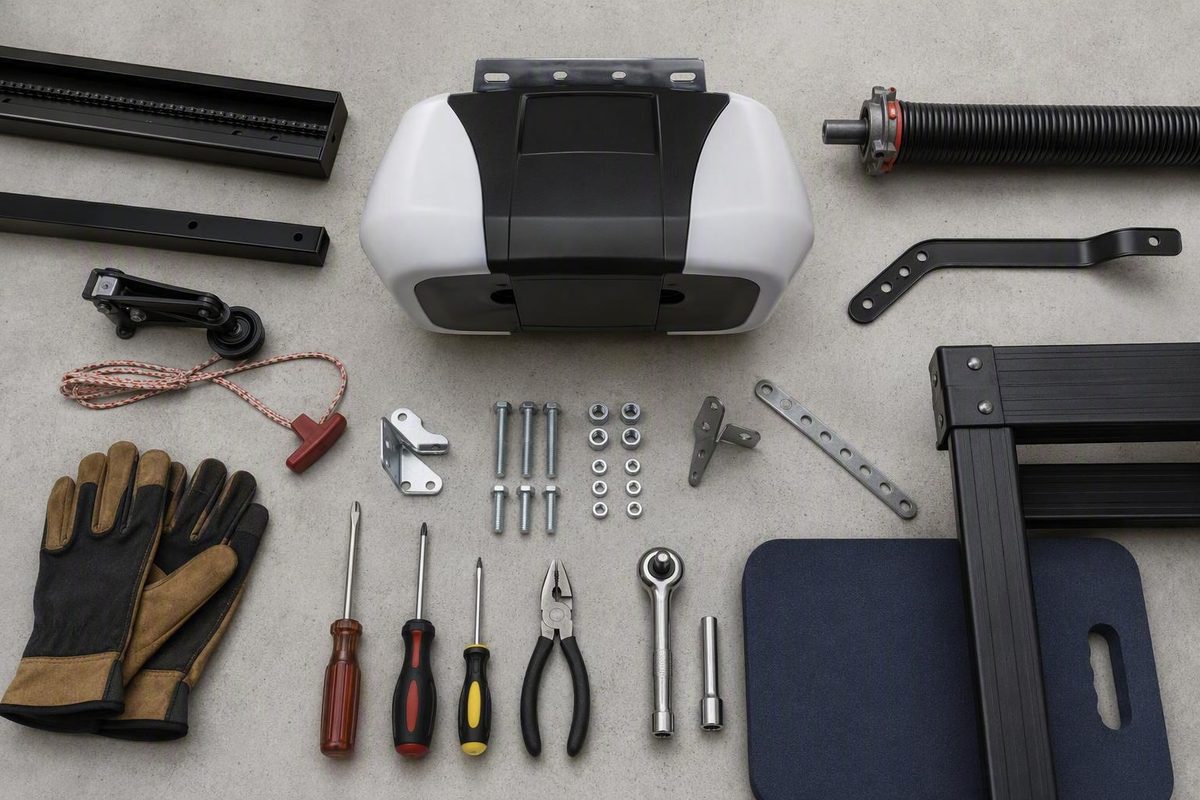
A safe LiftMaster 8500 installation starts before the opener is placed on the torsion bar. First confirm the exact model and applicable manual. Then verify that the door, torsion assembly, available clearances, mounting surface, electrical supply, and required safety components meet the documented conditions.
This LiftMaster 8500 installation guide is a manual-finding, compatibility, installation-overview, and commissioning checklist. It is not a complete installation procedure, and it does not replace the manual for the opener’s model and manufacturing period. Garage-door counterbalance and permanent-wiring work should be assigned to qualified professionals.
Start with the correct model and manual
Do not assume instructions for an 8500W apply to an original LiftMaster 8500. Although both are wall-mount openers, their documentation, accessories, electrical details, and setup procedures must be treated as model-specific unless the applicable manual expressly says otherwise.
Read the model number from the opener:
- Original 8500: The model-number label is behind the opener’s hinged door.
- 8500W: The model number is on the operator’s front cover.
The original manual describes the 8500 as a wall-mount opener for qualifying sectional doors with torsion assemblies. It also states that installation is intended for trained garage-door technicians and that the opener must not be powered or operated until the instructions direct the installer to do so. These model, application, and safety statements appear in the dealer-hosted LiftMaster 8500 manufacturer manual.
Chamberlain Group support provides separate original-8500 manual downloads for units manufactured before 2022 and units manufactured in 2022 or later. The available support information does not identify every difference between those versions or provide a universal method for decoding the manufacturing date on every original 8500. Select the applicable document through the official LiftMaster 8500 manual support page.
Because the available evidence does not provide verified original-8500 document numbers or direct official PDF paths for both periods, do not choose a manual by appearance alone. If the product label, purchase records, or support page do not make the correct period clear, stop and ask LiftMaster support or a qualified LiftMaster dealer to identify the applicable document.
Model-and-manual decision tree
Path 1: The label confirms an original 8500
- Record or photograph the complete label behind the hinged door.
- Determine whether the unit belongs to the pre-2022 or 2022-or-later documentation group using reliable product records or manufacturer support.
- Open the corresponding original-8500 manual.
- Confirm that the document identifies Model 8500.
- Use that one manual for compatibility, installation, wiring, adjustment, testing, and programming.
Path 2: The label confirms an 8500W
- Set aside instructions labeled only for the original 8500.
- Select the 8500W manual for the correct manufacturing period.
- Follow its model-specific electrical, accessory, networking, and commissioning instructions.
- Do not import an original-8500 step merely because the two openers look similar.
Path 3: The model or manufacturing period remains uncertain
- Do not begin mechanical work.
- Find and photograph the product label.
- Check purchase, installation, warranty, or dealer records.
- Obtain confirmation of the model and applicable manual.
- Resume only when the documentation clearly matches the opener.
8500W documentation sidebar
The official 8500W support page separates manuals for units manufactured before 2022 from those manufactured in 2022 or later. A Step Saver Setup sticker below the Learn button identifies a 2022-or-later 8500W. The later group uses a combined multilingual manual, while the earlier group has separate language downloads. See the official Chamberlain Group 8500W manual page.
A dealer index may use a combined “8500, 8500W” heading even when every listed document is labeled 8500W. The heading therefore does not prove that a file applies to the original 8500; inspect the actual document title and model designation. The Garage Headquarters manual index is one example.
Know where homeowner checks end and technician work begins
The original 8500 manual says the opener is intended for installation by trained garage-door technicians. Springs, cables, drums, shafts, brackets, pulleys, tracks, and related counterbalance hardware can be under extreme tension.
Reading an installation procedure is not equivalent to having the tools, training, and judgment needed to change spring tension, reset cables, reposition drums, alter tracks, or modify a torsion shaft. The safe boundary is observational: an owner can document conditions, but hazardous mechanical corrections belong to a trained door-systems technician.
Lower-risk checks an owner can document
Without loosening, repositioning, or disassembling door hardware, an owner can:
- Read and photograph the opener’s model label.
- Obtain the applicable manual.
- Identify whether the door is sectional.
- Observe whether the door uses torsion springs or extension springs.
- Measure accessible wall, ceiling, and side clearances.
- Record the torsion-bar diameter without removing hardware.
- Observe whether the bar appears to project beyond the bearing.
- Locate the intended outlet.
- Confirm whether the garage has another pedestrian entrance.
- Inventory the opener, controls, lock, monitor, sensors, light, wiring, and supplied hardware.
- Note visible damage, cable slack, unusual shaft movement, or track problems for the technician.
Do not turn those observations into instructions to loosen set screws, adjust spring tension, move drums, reset cables, change track geometry, or cut or replace a shaft.
STOP WORK
Do not mount, power, or operate the opener if the door:
- Binds or sticks during manual movement.
- Drops, rises unexpectedly, or will not remain properly balanced.
- Has loose, damaged, or displaced cables.
- Shows noticeable torsion-bar movement.
- Requires spring, drum, cable, shaft, bracket, pulley, or track changes.
- Has damaged wiring or an uncertain electrical connection.
Have a trained door-systems technician correct mechanical defects. Permanent wiring must be completed by a qualified person under the applicable electrical and building codes. The available third-party permanent-wiring excerpt is incomplete and must not be used as a stand-alone electrical procedure.
Do not bypass the Protector System safety sensors or cable-tension monitor. Both are required for normal closing. The 8500W guidance likewise assigns spring, cable, hardware, and track work to trained technicians, prohibits premature power connection, and requires permanent wiring to comply with applicable codes. It also prohibits extension cords, two-wire adapters, and plug modification for that model, as stated in the 8500W manufacturer user guide.
Use a pass-or-fail compatibility worksheet
Treat compatibility as a series of gates, not as a general impression that the opener “should fit.” One failed requirement is enough to stop installation until a qualified person establishes a supported solution.
The worksheet below applies to the original LiftMaster 8500. Its dimensions and operating limits are drawn from the original-model manufacturer manual. An 8500W owner should instead complete the checks in the applicable 8500W documentation. If you need help distinguishing opening, sideroom, headroom, and floor measurements, review this general guide to garage-door dimensions and measurement without substituting its generic figures for the model-specific values below.
| Compatibility item | Original-8500 requirement | Your finding | Pass/Fail |
|---|---|---|---|
| Door construction | Sectional door | ||
| Counterbalance system | Compatible torsion assembly; no extension springs | ||
| Track configuration | Standard lift or supported high lift; no unsupported low-headroom track | ||
| Torsion-bar diameter | 1 inch | ||
| Drum compatibility | 4–6 inches; no tapered drum over 6 inches | ||
| Door height | No more than 14 feet | ||
| Door width | No more than 18 feet | ||
| Door area | No more than 180 square feet | ||
| High lift | No more than the documented 54 inches, subject to the complete manual | ||
| Wall to torsion-bar center | At least 2.5 inches | ||
| Ceiling to torsion-bar center | At least 3 inches | ||
| Side obstruction to torsion-bar end | At least 8.5 inches | ||
| Bar projection beyond bearing | At least 1.5 inches, subject to the complete manual | ||
| Floor-to-door-bottom gap | No more than 0.25 inch | ||
| Door movement | Smooth, without binding or sticking | ||
| Door balance | Properly balanced | ||
| Mounting support | Solid framing or appropriate masonry support | ||
| Electrical supply | 120 Vac, 60 Hz supply within the six-foot cord reach |
These original-8500 limits—including the door dimensions, torsion-bar and drum sizes, clearances, shaft projection, floor gap, electrical supply, and maximum operating rate of 10 complete cycles per hour—are documented in the LiftMaster 8500 manufacturer manual.
Door and torsion-system gate
The original 8500 is limited to a compatible sectional door with a torsion assembly. An extension-spring door fails this check, as does an unsupported low-headroom track configuration.
The torsion bar must be 1 inch in diameter. Compatible drums fall within the documented 4-to-6-inch range, with tapered drums over 6 inches excluded. A shaft fitting inside the opener’s collar does not, by itself, establish compatibility.
The documented door limits are:
- Up to 14 feet high.
- Up to 18 feet wide.
- Up to 180 square feet in area.
- Standard-lift or qualifying high-lift operation, with high lift listed up to 54 inches.
Those dimensions do not prove that every high-lift door is supported. Drum design, track configuration, cable behavior, door balance, shaft condition, and the other requirements in the complete manual still control.
The supplied third-party evidence contains conflicting maximum door-weight figures, so this guide does not state a maximum weight. Resolve any weight-dependent question through the applicable manufacturer documentation or LiftMaster support.
Clearance and shaft gate
Measure from the exact reference points stated in the manual:
- Wall to torsion-bar center: at least 2.5 inches.
- Ceiling to torsion-bar center: at least 3 inches.
- Side wall or obstruction to torsion-bar end: at least 8.5 inches.
- Torsion bar beyond the bearing: at least 1.5 inches, subject to all other installation conditions.
The opener may be installed on the left or right side only when every model-specific condition is satisfied on that side. Available space alone is not enough; the shaft, bearing, drum, framing, wiring, power supply, lock, and cable-tension-monitor arrangement must also work.
A third-party commercial guide rounds some measurements to approximately 10 inches of sideroom, 4 inches above the shaft, and 2 inches of shaft projection. Those figures are not substitutes for the original manual’s stated reference points and minimums. The guide also gives conflicting door-weight claims, so its 8500/8500W overview should be treated only as supplemental commentary.
Floor and reversal gate
The gap between the floor and the bottom of the closed door must not exceed 0.25 inch for proper safety-reversal operation. Check the full width of the opening rather than measuring at one convenient point. An uneven or sloped slab may create an excessive gap at one side.
Do not respond to a failed floor condition by defeating the sensors or increasing force. Have the door-to-floor problem evaluated and corrected before commissioning.
Prepare the door, mounting surface and power supply
Preparation is complete only when the door operates correctly without assistance from the opener. Following the safe checking method in the applicable manual, the door should move smoothly without sticking or binding and should remain properly balanced.
If the door drops, rises unexpectedly, becomes difficult to control, binds in the tracks, or develops cable slack, stop. An automatic opener is not a repair for an improperly balanced or mechanically defective door.
Before installation:
- Disable existing manual locks so they cannot engage during opener operation.
- Remove ropes attached to the door.
- Clear stored objects and trip hazards from the work area.
- Plan wiring routes away from moving door and counterbalance components.
- Prevent accidental operation of controls while work is underway.
- Keep people away from the opening and torsion hardware.
Provide a structural mounting surface
The opener’s mounting bracket must attach to solid support. Drywall is a finish material, not a structural anchor.
Where the mounting position is over drywall, the fasteners must reach a stud or properly installed structural wood blocking. Masonry mounting requires anchors appropriate to the substrate and load. Do not rely on generic plastic wall plugs, drywall anchors, or an unverified masonry joint.
Materials may vary with the garage and component locations. The installer may need:
- Structural wood blocking.
- Suitable framing fasteners.
- Appropriate concrete or masonry anchors.
- Sensor or extension brackets.
- Supports for protected low-voltage wiring.
- Materials needed to provide a compliant nearby outlet.
This is not a universal shopping list. The applicable manual, actual construction, and installer’s assessment control.
Plan the power supply before mounting
The original 8500 requires 120 Vac, 60 Hz power, with an outlet normally needed within reach of its six-foot cord. Account for that condition before selecting the final mounting position. Do not plan to stretch, splice, pinch, or modify the power cord.
The cited 8500W guidance specifically requires a grounded outlet and prohibits extension cords, two-wire adapters, and plug modification. Original-8500 owners should follow the electrical rules in their own applicable manual rather than assuming every 8500W detail is interchangeable.
If the required supply is unavailable, have a qualified person provide it. Permanent wiring must comply with applicable electrical and building codes and must not be attempted from an incomplete online procedure.
Plan access during an outage
If the garage has no other entry door, address outage access before the wall-mount opener becomes the only practical route inside. The original 8500 manual strongly recommends the Model 475LM battery backup in that situation because an external emergency-release mechanism cannot be used with the opener.
It addresses the separate problem of reaching the opener when no secondary garage entrance is available.
Understand the supported mounting requirements
The following is a high-level mounting map to use beside the complete applicable manual. It is not an independent mechanical installation sequence and does not authorize cutting a shaft, changing springs, resetting drums, moving cables, or altering tracks.
Collar orientation
The collar has different-sized openings. Its larger opening goes onto the opener’s motor shaft, and its set screws face outward so they remain accessible.
Before tightening anything, confirm that the collar and mounting bracket match the assembly shown in the applicable manual. Do not infer orientation from a photograph of another model or revision.
Position on the torsion bar
The opener slides onto the torsion bar while the collar remains clear of the bearing. The original manual’s diagram specifies at least 0.25 inch between the collar and bearing.
Do not force the opener into place or relocate counterbalance hardware to make it fit.
Alignment before drilling or final fastening
Before mounting holes are finalized, the opener must be:
- Vertically aligned.
- Positioned at a right angle to the torsion bar.
- Supported in its intended operating orientation.
- Located so the collar remains clear of the bearing.
- Aligned with solid framing or suitable masonry support.
Noticeable torsion-bar movement must be corrected before commissioning because the original manual warns that it can greatly reduce opener life.
Set-screw guidance is shaft-specific
Where the applicable original-8500 manual confirms the same assembly and shaft type, the documented turn-based guidance after the set screws contact the torsion bar is:
- Hollow torsion bar: three-quarters to one full turn.
- Solid shaft: one-quarter to no more than one-half turn.
On a keyed torsion bar, the set screws must not be tightened into the keyway. These are turn-based directions, not torque specifications. Do not invent a torque value or substitute a generic fastener chart.
A third-party reproduction of the 8500 mounting procedure includes the collar clearance, alignment, solid-support, set-screw, and keyed-shaft instructions. Use it only as supplemental material beside the complete model-specific manual.
If the shaft is damaged, too short, incorrectly positioned, or otherwise incompatible, stop. This guide does not provide instructions for cutting the shaft or altering springs, drums, cables, bearings, or tracks.
Place every control and safety component correctly
Component placement affects hazard detection, door security, manual release, and operation. Use the complete manual for exact bracket orientation, fasteners, wiring routes, terminal assignments, and testing.
| Component | Documented placement | Function | Pre-power check |
|---|---|---|---|
| Emergency release | Reachable; source wording conflicts between at least 6 feet above the floor and no higher than 6 feet | Allows manual release from inside | Confirm the applicable manual and local requirements; ensure unobstructed access |
| Wall control | Visible from the door, away from moving parts, at least 5 feet above adjacent walking surfaces | Operates and programs the opener while remaining out of small children’s reach | Confirm height, visibility, protected wiring, and clearance |
| Power door lock | Under the applicable manual; a detailed third-party procedure places it within 10 feet of the opener and often at the second roller from the bottom | Prevents manual opening after the door closes | Confirm side, roller relationship, wiring, and free movement |
| Cable-tension monitor | In the model-specified position beside the cable system | Detects loss of cable tension and is required for normal downward operation | Confirm mounting, connection, sensing condition, and protected wiring |
| Safety reversing sensors | Facing each other across the inside of the doorway, with the beam no more than 6 inches above the floor | Detect an obstruction during closing | Confirm matched height, alignment, unobstructed beam, brackets, and wiring |
| Remote light | As directed by the model manual, using a standard 120 V outlet | Provides illumination and visual programming confirmation | Confirm secure placement, outlet suitability, and model-specific lamp requirements |
| Opener mounting bracket | Solid framing or appropriate masonry support | Restrains and aligns the opener | Confirm that fasteners do not rely on drywall alone |
The detailed original-8500 installation reproduction supports the lock’s 10-foot placement, the cable-tension-monitor requirement, the 5-foot control height, the 6-inch sensor height, and the standard 120 V outlet for the remote light. It also reports that interrupting the sensor beam during closing causes a full reversal and 10 opener-light flashes. These details appear in the third-party 8500 installation procedure, which must yield to the applicable manual.
Emergency-release conflict
The available original-8500 material contains conflicting wording. General safety language says the release must be reachable and at least 6 feet above the floor, while the detailed installation step says the handle should be no higher than 6 feet.
Do not resolve that discrepancy by selecting whichever statement is more convenient. Follow the exact manual applicable to the unit and any local requirements. If compliant placement remains unclear, obtain manufacturer or qualified-installer guidance before operation.
Power lock and cable-tension monitor
The power door lock prevents the fully closed door from being opened manually. The third-party installation procedure’s 10-foot and second-roller details are supplemental; the applicable model and revision manual control.
The cable-tension monitor is required. If it is missing, disconnected, incorrectly mounted, or unable to detect the required cable condition, the opener will not normally move the door downward. Never bypass it to make the door close.
Protector System sensors
The safety reversing sensors face each other across the inside of the doorway, with the beam no more than 6 inches above the floor. Both brackets must be secure, the wiring protected, and the beam correctly aligned.
The Protector System and cable-tension monitor must both be connected and properly aligned before normal closing will occur. An illuminated indicator does not replace the model-specific alignment and functional tests.
Remote light
The remote light uses a standard 120 V outlet and provides visual confirmation during programming. Install it according to the applicable model manual, including its permitted location, mounting method, outlet arrangement, and lamp specification.
Do not apply a universal bulb rule to every 8500 and 8500W revision. Lighting and radio-frequency considerations may vary by model, accessory, and manual revision.
Commission the opener without confusing the controls
Commissioning begins only after the mechanical installation and required safety components have been inspected.
Before connecting power, confirm:
- [ ] The exact model and applicable manual are known.
- [ ] The opener and mounting bracket are secure.
- [ ] The opener is vertical and at a right angle to the torsion bar.
- [ ] The collar does not contact the bearing.
- [ ] The door remains smooth and properly balanced.
- [ ] Existing manual locks are disabled as required.
- [ ] Ropes formerly attached to the door have been removed.
- [ ] The power lock is mounted and connected as directed.
- [ ] The cable-tension monitor is installed and connected.
- [ ] Both safety reversing sensors are installed, aligned, and connected.
- [ ] Control and sensor wiring is protected from sharp edges, staples, and moving parts.
- [ ] The emergency release is installed under the controlling requirements.
- [ ] The electrical supply matches the applicable instructions.
- [ ] No spring, cable, drum, shaft, track, bearing, or wiring problem remains unresolved.
Use the right controls for the right task
Do not treat every button as a general programming control.
| Task | Correct control |
|---|---|
| Program compatible Security+ 2.0 accessories | Learn button on the myQ Control Panel |
| Set travel | Black and yellow buttons on the opener, following the applicable manual |
| Set force | Black and yellow buttons on the opener, following the applicable manual |
| Diagnose failed remote pairing | Accessory-programming procedure, not the travel or force controls |
Diagnostic codes are not available during travel setup, so their absence at that stage does not establish another fault. The official original-8500 support instructions distinguish the control-panel Learn button from the opener’s black and yellow travel-and-force buttons.
Use the complete applicable manual for the actual travel and force sequence. The available excerpts are not continuous enough to reproduce that procedure safely. Do not construct a hybrid sequence from an 8500W video, an original-8500 excerpt, and a generic opener tutorial.
Test each safety and security function separately
After travel and force have been set under the applicable manual, test:
- Cable-tension monitor: Confirm the specified response when the monitored cable condition changes.
- Power door lock: Verify engagement and release without interference with roller travel.
- Protector System: Verify alignment and the specified response to an interrupted beam.
- Emergency release: Test release and reconnection with the door controlled and the area clear.
- Safety reversal: Confirm reversal on the prescribed test object.
For the contact-reversal test, place either a 1.5-inch-high object or a 2-by-4 laid flat beneath the door, as specified by the manual. The door must reverse on contact. If it does not, stop using the automatic opener until the system has been adjusted and successfully retested.
The cited original-8500 procedure also reports that interrupting the sensor beam while the door is closing makes the door stop, reverse fully, and flash the opener lights 10 times. Treat that behavior as a clue for the applicable original 8500, not as a universal diagnostic code for every model or revision.
8500W-only Wi-Fi note
This networking information applies only to a confirmed 8500W. Wi-Fi setup requires:
- A 2.4 GHz 802.11b/g/n network.
- Broadband internet.
- A compatible connected device.
- The password for the main network.
Those requirements, along with the 8500W safety-reversal test using a 1.5-inch object or a flat 2-by-4, appear in the 8500W manufacturer user guide.
Do not interpret the absence of Wi-Fi functions on an original 8500 as an installation failure, and do not blend 8500W app instructions into original-8500 mechanical commissioning.
The original 8500 must not exceed 10 complete door cycles per hour. If the intended use regularly requires more, do not assume the opener is suitable merely because it can move the door during an initial test.
Troubleshoot no-close and access problems safely
When a newly installed opener will open but not close normally, begin with the required safety devices—not the force setting.
No-close diagnostic flow
1. Check the Protector System
- Are both sensors securely mounted?
- Are they facing each other?
- Is the beam no more than 6 inches above the floor?
- Do the indicators show the alignment state specified in the manual?
- Is anything obstructing the beam?
- Is either bracket bent or vibrating?
- Is wiring cut, pinched, reversed, loose, or exposed to moving hardware?
2. Check the cable-tension monitor
- Is the required monitor present?
- Is it mounted in the correct model-specific position?
- Is its wiring intact and connected to the specified terminals?
- Is it sensing the cable condition required by the manual?
- Does recurring cable slack indicate a mechanical door problem?
Both systems must be connected and properly aligned for normal closing. Correct a failed installation under the applicable instructions rather than disabling the device.
3. Observe the behavior
For the cited original-8500 procedure, interrupting the sensor beam during closing produces a full reversal and 10 opener-light flashes. That response can point toward an obstruction or alignment problem, but it is not a universal fault code.
4. Recheck the door
Disconnect and check the door only through the safe method in the applicable manual. Stop if it binds, sticks, becomes unbalanced, or develops cable slack.
5. Keep pairing separate from travel
A remote that will not pair presents an accessory-programming issue. Use the Learn button on the myQ Control Panel for compatible Security+ 2.0 accessories. Do not respond by pressing the black and yellow travel-and-force controls.
Supplemental original-8500 light-button tip
For an original 8500, the manufacturer’s supplemental procedure for assigning the opener light to an unused compatible remote button is:
- Close the garage door.
- Press and hold an unused button on the remote.
- Press and hold the Lock button on the myQ Control Panel.
- Press and hold the control-panel Light button.
- Release the buttons after the opener lights flash.
If bulbs are absent, two clicks indicate completion. This light-control procedure does not work with universal remote controls and does not replace the standard remote-pairing, travel, or force procedures.
Plan for loss of power
If the garage has no secondary entrance, do not wait for an outage to discover that the interior emergency release is inaccessible. Act on the original manual’s battery-backup recommendation before the opener becomes the only practical route into the garage.
Confirm that the backup is compatible, installed correctly, and tested under its own instructions. Test the interior emergency release separately while access is available and the door is in a safe condition.
Escalate instead of experimenting
Stop troubleshooting and call a qualified technician if you find:
- Damaged or uncertain wiring.
- Recurring cable slack.
- Noticeable torsion-bar movement.
- A door that binds, sticks, drops, rises, or will not remain balanced.
- A broken, displaced, or questionable spring.
- Drum, bearing, shaft, bracket, roller, or track damage.
- A safety sensor or cable-tension monitor that cannot be installed correctly.
- Repeated reversal-test failure.
- Unexplained no-close behavior after the documented checks.
- A need to increase force merely to overcome resistance.
Frequently asked questions
Can I install a LiftMaster 8500 on a door with extension springs?
No. The original LiftMaster 8500 is intended for a compatible sectional door with a torsion assembly. A door using extension springs fails the documented compatibility requirements.
Converting an extension-spring door to a torsion system is not part of mounting the opener. It involves springs, shafts, drums, cables, brackets, and structural considerations that require evaluation by a trained door-systems technician.
Can the LiftMaster 8500 be installed on either side of the garage door?
Yes, but only if the chosen side satisfies every requirement in the applicable original-8500 manual. That includes wall, ceiling, and side clearances; shaft projection; bearing and drum arrangements; structural support; opener alignment; component placement; wiring; and power availability.
The fact that the opener can physically slide onto one end of the shaft does not establish that the side is acceptable. If one side fails a requirement, evaluate the other side against the complete worksheet rather than improvising around the obstruction.
Why will my LiftMaster 8500 open but not close after installation?
Begin with the Protector System safety sensors and required cable-tension monitor. The opener will not close normally unless both systems are connected and properly aligned.
Check sensor height and alignment, remove beam obstructions, inspect wiring, and confirm correct cable-tension-monitor installation. Then look for cable slack or a binding, sticking, or unbalanced door. Do not increase force to conceal mechanical resistance.
If those checks pass, follow the troubleshooting sequence in the exact manual for the opener’s model and manufacturing period.
Which button programs a LiftMaster 8500 remote?
Compatible Security+ 2.0 accessories are programmed with the Learn button on the myQ Control Panel. The opener’s black and yellow buttons are reserved for travel and force programming.
Do not alter travel or force because a remote will not pair. Confirm accessory compatibility and follow the applicable original-8500 programming instructions.
When is battery backup especially important for a LiftMaster 8500?
Battery backup is especially important when the garage has no other entry door. The original 8500 cannot use an external emergency-release mechanism, so an outage could otherwise make the interior release inaccessible from outside.
The original manual strongly recommends the Model 475LM battery backup for that situation. Plan access before relying on the opener as the garage’s only practical entrance, and test the compatible backup and interior emergency release under their respective instructions.
Make the final go-or-no-go decision
Proceed only when all three conditions are satisfied:
- The model and applicable manual are confirmed.
- The door, torsion assembly, clearances, mounting surface, power arrangement, and workspace pass every compatibility check.
- A trained professional handles hazardous door-hardware corrections and permanent electrical work.
Before normal use, verify that the opener is securely mounted, the collar is clear of the bearing, the cable-tension monitor is connected, the safety sensors are aligned, the power lock and emergency release work correctly, travel and force have been set under the applicable manual, and the obstruction-reversal test succeeds.
If any question remains about the model, manual period, door balance, clearance, shaft, wiring, or safety system, stop. Do not compensate with higher force settings, improvised dimensions, mixed-model instructions, or bypassed safety devices.