
How to Plan a Garage Floor That Fits the Ground, Loads, and Climate
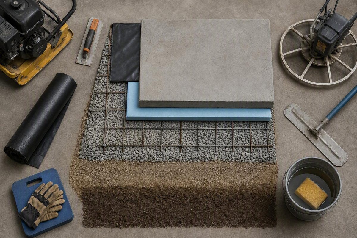
A durable garage slab is not selected by thickness alone. It works as a system: the ground, compacted base, moisture control, insulation, reinforcement, concrete mixture, drainage, joints, finishing, curing, foundation edges, and imposed loads all affect performance.
That is why two apparently similar garages may need different slabs. A four-inch floor is commonly presented as a starting concept for ordinary passenger-vehicle parking on stable, uniformly prepared ground (MudMixer’s garage-slab guide). The same thickness may be unsuitable for expansive soil, deep fill, an RV, heavy machinery, or a two-post vehicle lift.
Scope note: The ranges below are planning aids for discussions with contractors, suppliers, building officials, and designers—not an executable construction specification. The available garage-specific sources are predominantly commercial guides and trade discussions rather than governing codes, concrete standards, geotechnical reports, or model-specific equipment manuals. Local requirements, approved drawings, site conditions, and exact manufacturer instructions take priority.
Start With the Slab’s Job, Site, and Required Foundation System
A slab on grade is a concrete floor supported continuously by prepared ground. It generally is not intended to bridge substantial soft spots, settlement, or voids. Just as important, the floor slab is not automatically the complete foundation for the garage.
Depending on the climate, soil, building type, and local requirements, the project may need one or more of the following:
- Separate footings and stem walls
- Frost walls or frost-protected construction
- Thickened slab edges
- Grade beams
- Pier foundations
- A monolithic slab-and-footing system
- A specially engineered structural or post-tensioned slab
Resolve that distinction before excavation. Pouring a flat floor where an approved foundation system was required can leave an otherwise attractive slab unsuitable for the planned building.
Define the garage before designing its floor
Create a written load and use schedule. At minimum, record:
- Finished garage length and width
- Attached or detached construction
- Wall and roof system
- Number and size of garage-door openings
- Passenger cars, SUVs, pickups, trailers, or motorcycles
- RVs, motorhomes, or unusually heavy vehicles
- Vehicle-lift type, model, capacity, and possible post locations
- Workbenches and floor-mounted machinery
- Storage racks and concentrated leg loads
- Interior partitions or masonry features
- Floor drains and plumbing
- Electrical conduit and sleeves
- Radon piping where applicable
- Hydronic radiant tubing
- Under-slab insulation
- Planned floor coating or adhered finish
- Snowmelt, rain, wash water, vehicle fluids, and other drainage demands
Do not describe the project merely as “a two-car garage.” One such garage may hold two compact cars; another may contain a heavy pickup, pallet racking, a milling machine, and a two-post lift. The footprints may be similar, but the load paths are not.
Also decide whether future flexibility matters. A floor intended only for passenger-car parking today may later be expected to support storage racks, machinery, or a lift. That possibility does not justify guessing at a heavier design, but it should be discussed before the slab is poured.
Resolve local requirements before digging
Ask the building department which permits, drawings, inspections, and site approvals are required. Relevant rules may address setbacks, building location, footing depth, frost protection, slab thickness, reinforcement, anchorage, termite measures, radon provisions, drains, discharge, and finished-floor elevation. Commercial garage-foundation guidance likewise recommends resolving zoning, setbacks, permits, footing requirements, and inspections before construction begins (Sheds Unlimited’s garage-pad guide).
Arrange the applicable utility-location service before excavation.
Establish inspection hold points as well. The contractor should know which work must remain visible before it is covered, including possible footing excavations, reinforcement, under-slab utilities, insulation, vapor-control details, and anchor assemblies.
Evaluate constructability
Concrete placement is time-sensitive. Before ordering concrete, determine:
- Whether a delivery truck can reach the site
- Whether the driveway, culvert, or yard can support the truck
- Whether a pump, conveyor, power buggy, or wheelbarrows are needed
- Where trucks and equipment can wash out lawfully
- How many workers the placement and finishing require
- Whether all screeding, floating, finishing, jointing, and curing equipment is on site
- How the work will be protected if weather changes
- How a delayed truck or interrupted placement will be handled
Restricted access can therefore change the delivery method, crew requirements, and placement sequence.
Know when to stop and obtain professional review
Seek local geotechnical, structural, or foundation advice when the site includes:
- Expansive clay
- Peat, organics, or buried debris
- Uncontrolled or undocumented fill
- Soft, wet, pumping, or unstable soil
- High groundwater
- A substantial transition between cut and fill
- Steeply sloping ground
- Frost-susceptible soil
- Heavy masonry or structural partitions
- Unusual concentrated loads
- A vehicle lift without finalized specifications
- Uncertainty about whether the slab is a floor, foundation, or both
General guidance can help identify questions and coordinate decisions. It cannot classify a particular site, select its foundation system, or certify a slab for a specified load.
Choose Thickness by Load—Not by a Universal Rule
Four inches is a commonly cited starting thickness for a residential garage used for passenger-vehicle parking. It is not a universal minimum or a guarantee of adequacy. Suitability also depends on support uniformity, concrete properties, exposure, reinforcement and joint design, actual loads, foundation details, and local requirements.
The following ranges are illustrative planning concepts reported in commercial guidance—not specifications for ordering concrete (SlabCalc’s garage-floor thickness guide):
| Intended use | Common planning concept | Conditions that could change it |
|---|---|---|
| Passenger cars and ordinary residential storage | Around 4 inches | Poor soil, frost, local rules, wall loads, unusual storage, drainage details |
| Light trucks or moderate workshop use | Often around 5 inches | Equipment feet, moving loads, partitions, base conditions |
| RVs, motorhomes, heavy trucks, or heavier equipment | Often 5–6 inches or project-specific design | Actual axle loads, tire loads, edges, exposure, foundation system |
| Vehicle lift | Exact manual and approved design | Lift type, rated capacity, anchors, reinforcement, concrete strength, joints, slab age |
| Difficult soil or unusual building loads | Engineered assembly | Thickness alone is not an adequate design method |
Published guidance is not consistent. One commercial source describes six inches as usual, while other sources use four inches as a residential baseline and UK supplier guidance provides a broader range based on loading. That disagreement is itself a reason not to treat an internet table as a governing specification (Miracle Truss’s garage-floor article).
Why thickness is only one variable
A slab transfers load to its supporting ground. If that support is continuous and reasonably uniform, an ordinary parking load is spread through the slab and base. If part of the support settles, heaves, or washes out, the slab must bend across the resulting difference.
Additional thickness can increase stiffness and provide margin when it is part of a coherent design. It does not correct:
- Loose or uncompacted fill
- Organic soil
- Expansive clay
- Pumping subgrade
- Poor edge support
- Variable excavation depth
- Inadequately restored utility trenches
- Erosion or washout
- Frost heave
- Unresolved groundwater
Minimum compliance and a durability upgrade are also different questions. A local authority may accept one assembly, while an owner chooses a more robust design because of expected trucks, harsh exposure, or future use. That upgrade still requires compatible reinforcement, joints, edges, concrete, and support.
Distributed loads and point loads are not equivalent
A parked vehicle distributes its weight through several tire contact areas. Machinery may place much of its weight on four small feet. Storage racks can impose concentrated reactions at narrow baseplates. A two-post lift introduces concentrated post reactions and anchor forces.
Consequently, the statement that a vehicle weighs less than a lift’s rated capacity does not establish that a parking slab can support the lift. Lift capacity, actual vehicle weight, front-to-rear load distribution, post reactions, anchor behavior, slab condition, and the support below the slab are separate inputs.
When the garage departs from ordinary residential parking, move from a generic thickness range to a project-specific specification.
Build Uniform Support From the Subgrade Up
A slab on grade needs continuous, reasonably uniform support. The average bearing capacity of the site tells only part of the story: differential movement between adjacent areas can bend and crack the slab even when the ground can support the total weight.
Think of the work beneath the concrete as a sequence:
- Existing soil or approved fill
- Removal or correction of unsuitable areas
- Compacted subgrade at the required elevation
- Compacted granular base
- Utility trenches restored as specified
- Moisture, insulation, and other under-slab components
- Concrete slab and edge or foundation details
A practical preparation sequence
First, strip vegetation, roots, organic material, and unsuitable topsoil. Do not bury stumps, construction debris, or soft material beneath the floor. Identify previously filled areas and utility trenches because these often compact differently from undisturbed ground.
Next, excavate or fill to the designed subgrade elevation. Do not make a large elevation change with one deep layer of loose material. Place approved fill in controlled lifts and compact each lift with equipment suited to the material.
Generic sources disagree about lift thickness. That is not a choice between two universally valid numbers: the material, moisture condition, equipment, required density, and project specification should determine how the fill is placed and verified.
Then place and compact the granular base. Approximately four to six inches of compacted crushed aggregate recurs in general garage guidance, but the correct depth remains site-specific (Sheds Unlimited’s base-preparation guidance).
Well-graded crushed material contains a range of particle sizes that can interlock and compact with fewer large voids. “Gravel,” however, is not a complete purchase specification. Rounded, uniformly sized stone behaves differently from a graded crushed product containing fines. Local soil, drainage, capillary control, radon measures, and membrane placement may favor a particular material.
Compaction must match the material
Compaction is not simply driving over the area until it appears firm. The process depends on:
- Soil or aggregate type
- Moisture content
- Loose lift thickness
- Compaction equipment
- Number of passes
- Edge access
- Required density
- Testing method
An informal hand-squeeze check may reveal material that is obviously saturated or powder dry. It cannot classify the soil, identify expansive behavior, establish a moisture-density relationship, or verify field density. Where the consequences are significant, use a defined compaction requirement and appropriate testing.
Inspect the entire footprint, not just the accessible center. Forms, existing walls, plumbing trenches, thickened edges, and equipment-pad excavations can prevent compactors from reaching critical locations.
Stop-work conditions
Pause excavation or base placement if you find:
- Soil that pumps under foot or equipment
- Deep ruts that do not stabilize
- Standing groundwater
- Buried organics, trash, or demolition debris
- Unrecorded fill
- Expansive clay
- A sharp transition from excavation into deep fill
- Voids around pipes
- A base that shifts under construction traffic
Do not answer weak support by casually ordering more concrete. Added thickness may increase stiffness, but it does not make variable or moving ground uniform.
Plan Moisture Control, Insulation, Drainage, and Penetrations Together
The under-slab assembly must be coordinated before reinforcement is placed. A vapor barrier, insulation, radiant tube, drain body, conduit, or sleeve cannot be added correctly after placement begins.
Vapor control is one part of water management
An under-slab vapor barrier limits water-vapor transmission from the ground. It does not replace:
- Positive exterior grading
- Roof-water control
- Groundwater management
- Perimeter drainage where needed
- A suitable granular base
- Correct door and threshold details
- Repair of plumbing leaks
Common detailing includes a continuous specified membrane, overlapped and taped seams, sealed penetrations, and edges terminated or turned up as required by the assembly.
Do not select membrane thickness or location from a single generic article. The decision can depend on jurisdiction, regional concrete practice, sub-slab material, radon strategy, and whether the finished floor will receive epoxy, adhesive, tile, or another moisture-sensitive finish.
Coordinate heated slabs before placement
For a heated garage, finalize the insulation assembly and radiant design before forming the pour. Confirm:
- Insulation type and compressive suitability
- Perimeter thermal details
- Required layer order
- Tube spacing and zones
- Manifold position
- Sleeve and transition protection
- Conflicts with reinforcement
- Equipment and lift-post exclusion zones
Secure the tubing against movement and pressure-test it before concrete placement. Do not prescribe a universal insulation thickness or assume that insulation can continue unchanged beneath highly concentrated equipment loads. Those details belong in the approved assembly.
Drainage is a complete system
A sloped floor cannot correct poor exterior drainage. Coordinate the finished slab with:
- The garage-door threshold
- Apron and driveway elevations
- Surrounding grade
- Floor drains where permitted
- Snow and ice melt
- Wind-driven rain
- Vehicle washing
- Oil, fuel, coolant, and chemical spills
- Applicable discharge and containment rules
- Equipment that requires level bearing surfaces
A fall of approximately one-eighth to one-quarter inch per foot toward the garage door is commonly cited, but it is not universal. The final slope must suit local requirements, door sealing, drain locations, lift tolerances, accessibility, parked equipment, and the intended use (SlabCalc’s garage-floor drainage guidance).
Mark high and low points on the drawings. Do not expect finishers to invent the drainage plan while screeding. A decorative finish cannot correct the wrong threshold elevation or a floor that drains toward the building.
Freeze the penetration plan
Before the pour, approve every item crossing or embedded in the slab:
- Floor drains and traps
- Water and waste piping
- Electrical conduits
- Radon piping
- Grounding components where required
- Sleeves
- Insulation
- Radiant tubing
- Anchor templates
- Equipment recesses
- Lift zones
- Future partition locations
Record concealed components with dimensions and photographs before they disappear.
Alternative garage floors made from plywood, foam, pavers, or loose aggregate may reduce concrete use in some situations, but they leave project-specific questions about fire compliance, concentrated vehicle loads, spills, moisture, drainage, durability, and cleanability. Treat such systems as assemblies requiring validation, not as interchangeable substitutes for a concrete slab.
Use Reinforcement and Joints for Their Actual Purposes
Concrete shrinks as it dries and responds to temperature, restraint, loading, and movement in its support. Reinforcement and joints help manage those behaviors; they do not promise a crack-free floor.
Mesh, rebar, and fibers do different jobs
Welded wire reinforcement is commonly used to restrain crack width and help hold cracked sections together. Its effectiveness depends heavily on placement, continuity, and support.
Conventional reinforcing bars provide more deliberate reinforcement for designed load conditions, edges, concentrated loads, or other specified locations. Bar size, spacing, laps, development, cover, and termination must match the approved design.
Ordinary synthetic fibers can reduce some early-age plastic-shrinkage cracking and improve cohesion. They should not automatically be treated as a replacement for specified steel reinforcement.
These functions are distinct, and none guarantees that concrete will not crack. Trade guidance similarly distinguishes steel that holds cracks together from ordinary fibers intended primarily to reduce some early-age cracking (Garage Journal’s floor-slab guide).
A project may use one, several, or none of these systems depending on the approved design. Generic tables prescribing one bar size and spacing cannot account for slab depth, support, exposure, openings, joints, loads, and foundation edges.
Position matters as much as presence
Reinforcement lying on the aggregate base is not at its intended elevation. Use proper chairs, bolsters, or other approved supports that can remain stable under worker traffic and concrete placement.
Do not plan to hook and pull an entire mat upward during the pour. That creates uncertain cover and uneven positioning. Workers, hoses, buggies, and rakes can also displace reinforcement, so inspect it immediately before placement and monitor it as work proceeds.
Know the joint types
Control joints, also called contraction joints, create weakened planes intended to encourage shrinkage cracks at planned locations.
Isolation or expansion material separates the slab from fixed elements such as columns, walls, or adjacent structures where independent movement is required.
Construction joints occur where separate placements meet. They should be designed and located rather than treated as accidental stopping points.
Cracks are unplanned separations. A crack does not automatically indicate structural failure, but its width, vertical displacement, movement, location, and cause matter.
Several garage guides recommend control-joint depth of approximately one-quarter of the slab thickness. Commercial guidance also often suggests joint spacing of roughly eight to twelve feet, but the final layout must reflect slab geometry, thickness, restraint, openings, and placement sequence (MudMixer’s joint-planning guidance).
Plan joints before placement, paying particular attention to:
- Re-entrant corners
- Door openings
- Columns
- Drains
- Pits and recesses
- Abrupt changes in slab width
- Equipment pads
- Thickened regions
- Future lift-post and anchor zones
Lift posts cannot simply be shifted a few inches after the door clearances, vehicle position, ceiling obstructions, and joint pattern have been fixed. Coordinate those systems on one plan.
Specify, Place, Finish, and Cure the Concrete as One Process
Concrete strength is not the only mix decision. The mixture must account for placement method, finishing, climate, moisture, freeze-thaw exposure, deicing salts, aggregate, slab thickness, curing, and intended loads.
Several commercial garage guides cite compressive strengths in the range of 3,000 to 4,000 PSI. Treat that as generalized market guidance, not a project specification. Air entrainment is similarly context-sensitive: guidance for an interior steel-troweled slab may differ from the regional specification for concrete exposed to freezing while wet (Garage Journal’s mix and finishing discussion).
The concrete supplier, contractor, designer, and applicable local requirements should determine the mixture. Neither “always use air” nor “never use air” is a safe universal rule.
Do not improvise with water
Adding water can make concrete easier to move, but it changes the water-cement relationship and may reduce performance. If workability is inadequate, coordinate adjustments with the supplier rather than repeatedly adding uncontrolled water on site.
Planning affects workability. Concrete that must move through a pump, travel down a long chute, or be placed in hot wind requires different coordination from a direct-discharge indoor placement. Crew size and placement speed must suit the selected mixture and slab area.
Follow a controlled placement sequence
Before discharge begins:
- Verify form dimensions, bracing, squareness, and elevations.
- Confirm foundation and edge details.
- Inspect the subgrade and base.
- Check membrane seams, penetrations, and terminations.
- Verify insulation and radiant tubing.
- Confirm reinforcement size, spacing, laps, cover, and supports.
- Recheck drains, thresholds, slopes, anchors, and blockouts.
- Approve the joint plan.
- Confirm weather protection and curing materials.
- Make sure required inspections are complete.
During placement, follow the planned sequence: place, consolidate where needed, screed to elevation, float, finish, install or cut joints at the appropriate time, and begin curing. Avoid unnecessary interruptions that create unplanned construction joints.
Do not finish while bleed water remains on the surface. Aggressive finishing cannot rescue incorrect forms, elevations, or drainage.
Treat curing as construction, not cleanup
Curing controls moisture and temperature while concrete develops strength. Possible methods include:
- Plastic sheeting
- Damp coverings
- Water curing
- A compatible liquid curing compound
Select the method for the weather, surface finish, and any planned coating. Confirm compatibility and surface-preparation requirements with the coating and curing-product manufacturers before the pour.
Protect fresh concrete from rapid moisture loss in hot, dry, or windy weather. In cold conditions, protect it from freezing and maintain the specified curing temperature. A sunny day is not automatically favorable; heat and wind can accelerate surface drying.
Use different milestones for different activities
Concrete develops strength gradually. Initial set, form removal, walking, framing, vehicle parking, coating, and drilling lift anchors are not the same event.
Commercial guidance commonly uses the following as rough planning milestones:
- Approximately 24–48 hours before ordinary foot traffic
- Approximately 7–10 days before vehicle traffic
- Continued strength development toward the commonly referenced 28-day point
These are not universal permissions. Weather, mixture, curing, loading, coatings, and equipment requirements can change the schedule (Alan’s Factory Outlet’s slab-placement guide).
The contractor, supplier, engineer, coating manufacturer, and lift manufacturer may each impose different requirements. Do not use the earliest general milestone as permission for every later activity.
Common failure risks
Many garage-floor problems trace back to a short list:
- Inconsistent or poorly compacted support
- Unrepaired soft areas
- Excess added water
- An unsuitable concrete specification
- Displaced reinforcement
- Finishing over bleed water
- Incorrect elevations or drainage
- Shallow, late, or poorly located joints
- Rapid surface drying
- Freezing during early curing
- Premature vehicle or equipment loading
- Applying a coating before the slab is ready
A high specified compressive strength does not cancel these workmanship and site risks.
Treat Vehicle Lifts and Unknown Existing Slabs as Special Cases
Vehicle lifts are safety-critical installations. Do not approve one from slab thickness alone, and do not use a generalized garage article as the installation specification.
Two-post lifts concentrate post reactions and anchor forces at two relatively small bases. Four-post lifts distribute loads differently and may use different anchorage arrangements. That difference matters, but it does not make every four-post lift acceptable on every residential slab.
Obtain the exact manual before pouring
Select the lift—or at least the exact candidate model—while the slab is still being designed. Obtain the current manufacturer installation manual and confirm:
- Required slab thickness
- Minimum concrete compressive strength
- Reinforcement requirements
- Whether continuous concrete or local foundations are permitted
- Anchor type, diameter, length, and embedment
- Hole-cleaning and installation procedures
- Anchor torque
- Post spacing
- Clearances from edges, seams, joints, and cracks
- Slab flatness or slope limits
- Minimum concrete age
- Restrictions involving heated floors or post-tensioning
- Vehicle weight and load-distribution limits
- Whether engineering approval is required
Generalized lift sources range from approximately four inches for some light-duty cases to six or eight inches, or engineered local foundations, for heavier equipment. Those variations demonstrate why no universal lift-slab specification is safe; the exact manual must control (Redline Stands’ lift-slab overview).
Rated lift capacity, actual vehicle weight, weight distribution, arm configuration, anchor design, concrete condition, and base support remain distinct inputs.
Assess an existing slab systematically
For an undocumented slab, use this workflow:
- Review records. Look for drawings, permits, invoices, concrete tickets, reinforcement notes, and construction photographs.
- Inspect the garage. Note settlement, heaving, spalling, moisture, displaced cracks, seams, patches, deterioration, and joints.
- Map the proposed lift. Check doors, ceiling height, trusses, lights, openers, vehicles, and escape paths as well as the floor.
- Identify concealed hazards. Determine whether post-tensioning, utilities, or radiant tubing may be present.
- Verify properties as needed. Thickness, strength, reinforcement, voiding, and continuity may require professional scanning or testing.
- Obtain approval. Submit the findings to the lift manufacturer, installer, engineer, or authority required by the project.
Core sampling is one possible professional method for investigating slab thickness and concrete strength. Qualified parties should select the locations, testing procedure, repairs, and interpretation rather than treating one informal core as proof that the entire slab is adequate (Redline Stands’ existing-slab guidance).
Never drill or saw a slab that may be post-tensioned until a qualified technician has identified tendon locations. Specialist lift guidance expressly warns against drilling or cutting a post-tensioned floor without locating those concealed components (Automotive Lift Experts’ concrete guidance).
Do not universalize anchor setbacks
Generalized sources publish different setbacks from cracks, edges, and joints. Those figures are not interchangeable. Use the clearances in the exact current lift manual and approved slab design.
Keep post bases and anchors away from cracks, control joints, construction joints, seams, edges, and unsuitable patches as directed. Also verify anchor embedment, hole-cleaning procedures, torque, concrete condition, and interference with reinforcement or concealed services.
If the existing slab is inadequate, possible responses include:
- Engineered local post foundations or pads
- Removal and replacement of defined slab sections
- Complete slab replacement
- Choosing a different lift or location
A thin overlay or loose steel plate is not automatically a structural correction. Any repair must provide the thickness, continuity, anchorage, reinforcement, support, and geometry required by the approved design.
Finally, distinguish vehicle parking from lift installation during curing. General floor guidance may allow ordinary vehicle access earlier, while lift installation involves drilled anchors and concentrated forces. The exact lift manual, concrete data, and approved design govern.
Calculate the Pour and Decide Whether the Project Is Truly DIY
For a slab of uniform depth:
Cubic feet = length × width × actual concrete depth in feet
Then:
Cubic yards = cubic feet ÷ 27
Convert inches to feet before multiplying. A four-inch depth is 4/12 foot, not 0.4 foot.
For a 24-by-24-foot slab at a nominal four-inch thickness:
- 24 × 24 × (4/12) = 192 cubic feet
- 192 ÷ 27 = approximately 7.1 cubic yards
That aligns with the roughly seven-cubic-yard estimate given in a commercial slab guide, but it excludes thickened sections and site variation (Alan’s Factory Outlet’s concrete-volume guidance).
Calculate deeper components separately before adding them to the nominal floor volume:
- Thickened edges
- Footings and grade beams
- Lift foundations
- Equipment pads
- Ramps and aprons
- Depressed areas
- Drain sumps
- Over-excavated zones
- Steps or transitions
Then include a project-specific allowance for uneven excavation, form variation, spillage, and unavoidable waste. Do not base the order solely on nominal floor dimensions or assume the excavated base is perfectly level.
Plan delivery, access, and labor
A loaded truck can damage pavement, landscaping, septic components, or buried utilities. If the truck cannot safely approach the forms, arrange a pump, conveyor, power buggy, or another realistic placement method.
A garage slab is also a poor project for an undersized crew. Once discharge starts, the team must place, consolidate, screed, check elevations, float, edge, finish, and begin joint and curing work on schedule. Tools and materials that are “on the way” are effectively unavailable.
Before committing to DIY, ask whether the team has demonstrated experience with:
- Forming accurate drainage elevations
- Compaction and base grading
- Membrane and insulation detailing
- Reinforcement supports and laps
- Concrete ordering and workability coordination
- Continuous placement
- Screeding a wide bay
- Machine or hand finishing
- Timely joint cutting
- Weather protection
- Curing
Professional installation or supervision is especially prudent when the project involves uncertain soil, frost foundations, difficult access, extensive reinforcement, drains, radiant heat, a large uninterrupted placement, unusual finishes, or vehicle lifts.
Budget by scope, not a national square-foot shortcut
Published garage-slab prices vary widely in what they include and should not be treated as a universal budget. Request itemized pricing for:
- Surveying and layout
- Permits and inspections
- Excavation and disposal
- Imported fill and aggregate
- Compaction equipment and testing
- Groundwater or drainage work
- Footings, walls, and edge forms
- Vapor barrier
- Insulation
- Radiant heat
- Reinforcement and supports
- Concrete
- Short-load, waiting-time, or delivery charges
- Pumping or buggy placement
- Labor and finishing
- Joint cutting
- Curing materials
- Sealing or coating preparation
- Engineering and testing
Itemization makes bids easier to compare and exposes omissions before construction begins.
Pre-pour hold-point checklist
Do not release the concrete order until the responsible parties have approved:
- [ ] Building dimensions and slab footprint
- [ ] Foundation type, footing depth, and frost protection
- [ ] Finished-floor, threshold, and exterior elevations
- [ ] Drainage direction and permitted discharge
- [ ] Subgrade condition
- [ ] Fill material, lift placement, and compaction
- [ ] Aggregate type, depth, grade, and compaction
- [ ] Membrane seams, penetrations, and edge termination
- [ ] Insulation type and placement
- [ ] Radiant tubing layout and pressure test
- [ ] Drains, plumbing, conduit, radon pipes, and sleeves
- [ ] Reinforcement type, spacing, laps, cover, and supports
- [ ] Thickened edges, equipment pads, and lift zones
- [ ] Anchor templates and exclusion zones
- [ ] Control-, isolation-, and construction-joint layout
- [ ] Required inspections
- [ ] Concrete mixture and ordered quantity
- [ ] Truck access, pump or buggy plan, and washout
- [ ] Crew size, tools, and backup equipment
- [ ] Weather protection
- [ ] Curing method and materials
- [ ] Restrictions on walking, framing, parking, coating, and drilling
Frequently Asked Questions
Is a 4-inch garage slab thick enough for cars and light trucks?
It can be an appropriate starting point for ordinary residential parking when the slab has uniform support, suitable concrete, properly planned joints and curing, and local approval. Commercial garage guidance commonly cites at least four inches for basic residential use, subject to garage size and municipal requirements.
Do not treat four inches as universally sufficient. Heavy pickups, workshop machinery, storage racks, unusual soil, frost conditions, masonry loads, or a future vehicle lift should be evaluated separately.
How much compacted gravel should go under a garage slab?
Approximately four to six inches of compacted crushed aggregate is a recurring planning range in garage guides. UK supplier guidance similarly calls for at least 100 mm—about four inches—of compacted graded crushed stone and fines, but local soil and drainage conditions should determine the actual assembly (Heidelberg Materials’ garage-floor guide).
Remove organic and unsuitable material first, place approved aggregate in controlled lifts, and compact it appropriately. If the soil pumps, ruts, contains undocumented fill, or varies sharply across the site, stop and obtain site-specific direction rather than simply adding gravel.
Does every garage slab need a vapor barrier?
Not every jurisdiction or assembly uses identical details, but a vapor barrier is commonly considered where ground moisture could affect the slab, indoor humidity, coatings, adhesives, stored materials, or adjacent occupied space.
The membrane limits vapor transmission; it does not replace exterior grading, drainage, groundwater control, or a suitable base. Type, thickness, position, seam treatment, penetrations, and edge termination should follow the approved local assembly and any floor-finish requirements.
Can a vehicle lift be installed on an existing 4-inch slab?
Possibly for some lift models and qualifying slabs, but thickness alone cannot answer the question. Informal reports include model-specific manuals permitting four inches of reinforced concrete, while other installations use thicker local foundations or replacement sections. Those examples cannot be generalized to a different lift or slab (Garage Journal’s two-post-lift discussion).
The exact current lift manual must accept the slab’s thickness, strength, reinforcement, age, condition, anchor embedment, and clearances. For an undocumented floor, records review, inspection, scanning, cores, or other professional testing may be necessary. Do not drill until post-tensioning, utilities, and radiant lines have been ruled out or located.
How long should a garage slab cure before parking or installing a lift?
There is no single waiting period for every activity. General garage guidance may delay foot traffic for roughly 24–48 hours and vehicles for approximately 7–10 days, while concrete continues developing strength toward the commonly referenced 28-day point.
Lift installation is a separate milestone because it involves drilled anchors and concentrated forces. Specialist guidance commonly references a 28-day curing period, but the exact lift manual, concrete data, weather conditions, and approved design must govern (Automotive Lift Experts’ curing guidance). Coatings also have separate moisture and cure requirements, so a parking date is not automatic permission to coat or drill.
The central decision rule is simple: specify the garage slab as a complete system rather than choosing thickness in isolation. Define the building and loads, resolve foundation and frost requirements, verify the soil and compacted base, coordinate moisture and drainage details, support reinforcement correctly, and plan joints and curing before concrete arrives. A four-inch parking slab may be an appropriate starting concept in ordinary conditions; unusual soil, severe climate, heavy loads, or concentrated lift forces are reasons to stop relying on generic guidance and obtain qualified local design.